


All installations and services must be performed by qualified service personnel.
16
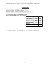
4. The total free area of openings in the floor or ceiling registers serving the return air
system must be at least 350 square inches. At least one register must be located
where it is not likely to be covered by carpeting, boxes, furniture, or any other
objects.
5. Materials located in the return air system must have a flame spread classification of
200 or less.
6. Wiring materials located in the return air duct system must conform to Article 300-22
of the latest edition of the National Electrical Code, NFPA 70.
7. Gas piping shall not be located in, or extend through, the return air duct system.
8. Refer to section G. COMBUSTION AIR for additional combustion air requirements.
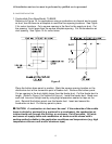
G. COMBUSTION AIR
The furnace requires the proper amount of combustion airflow through the combustion
air intake to combust the fuel cleanly and efficiently. An inadequate combustion air
supply can result in unsafe and erratic operation of the burner, sooting of the
combustion chamber and the heat exchanger, and possibly, offensive fuel odors. Refer
to chapter 5.3 of the National Fuel Gas Code, ANSI Z223.1 / NFPA 54-1999, or latest
edition for application specific combustion air requirements.
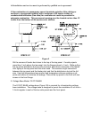
The preferred location of the outside combustion air intake terminal (e.g. an optional
stainless steel intake hood, part no.370183) is through the side of the structure, skirting,
or enclosure. An acceptable alternate location is under the structure in the skirted or
crawlspace area providing a minimum of 50 square inches of free area exists around
the perimeter for outside combustion air to be drawn through. The opening of the
termination must be at least 7 inches below the top of the floor.
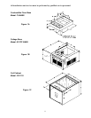
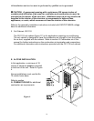
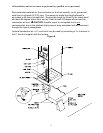
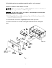
The 70-base/coil cabinet is shipped with a combustion air duct that must be installed in
the bottom of the base enclosure, before the furnace is installed. This 2-inch by 7-inch
duct is shipped in two pieces. High temperature silicone sealant should be applied to
both vertical seams, before it is snapped together with all four flanges on the same end.
High temperature silicone must be applied to the flanges. The combustion air duct can
then be inserted through the opening in the floor base model no.70. When the
combustion air duct has been inserted completely, secure the duct to the combustion
adapter with self-tapping sheet metal screws, refer to Figure 6. Make certain that the
flanges, duct, and adapter are completely sealed to the burner enclosure base with high
temperature silicone caulk. A 3-inch round to 7-inch x 2-1/4 inch rectangular adapter
plate is supplied with the furnace for adapting the 3-inch round flex combustion air duct
to the 2-inch x 7-inch combustion air duct.