


All installations and services must be performed by qualified service personnel.
25
it is mandatory the input to the burner be reduced 4.0% for every 1,000 feet that it is
above sea level. If the furnace is installed at an elevation of 5,000 feet, its input must
be reduced 20.0%. Example: a furnace rated at 80,000
BTU at sea level must be reduced to a firing rate of 64,000 (80,000 x .80 = 64,000) at
an elevation of 5,000 feet. If the furnace is installed at an elevation of 2,000 feet or
less, no reduction in input is required. Your gas supplier may supply you with the
correct orifice sizing information.
To check the heat input rate of your natural gas furnace, allow the unit to operate for 10
to 15 minutes and proceed as follows:
a. Call your gas supplier and ask for the BTU content (heating value) of one cubic foot
of the gas, supplied to the installation area. An alternate approach is to assume a value
of 1025 BTU/Cu Ft, which is the national average.
b. With all other gas appliances turned off and using a stopwatch, clock the time
required for the (small) dial on the gas meter to make one full revolution. The meter
dial will state the cubic feet of flow for one revolution usually one, two or five.
FORMULA: BTU/Cu Ft x Number of Cu Ft x 3600 Seconds = Input BTU/hr
Seconds for one revolution
EXAMPLE: 1025 BTU/Cu Ft x 2 Cu Ft x 3600 = 78,678 BTU Input
93.80 Seconds
Check the model number of the furnace, the input rate, the type of gas, and the
manifold pressure on the rating label located in the burner vestibule. If using the above
example, the furnace is a GMD1-80N model and the input rate is 78,678 BTU/hr. The
input rate would be acceptable because it was within + 2% of the listed input of 80,000.
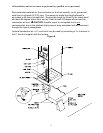
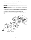
c. Make sure that the gas supply pressure to the furnace is within the allowable range of
5.5" to 14" WC pressure on natural gas and 11.0" to 14.0" WC on propane gas. The
pressure to the furnace must be checked while the furnace burner and any other gas
appliances on the same supply system are operating, using the 1/8 in. NPT manifold
pressure tap shown in figure 8.
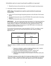
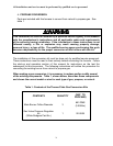
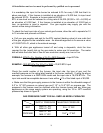
GAS PRESSURE CHART FOR ALL GMD1-80 MODEL FURNACES
SUPPLY PRESSURE MANIFOLD PRESSURE
NAT
MAX 14” WC
MIN 5.5” WC
3.5 + .3” WC
PROPANE
MAX 14” WC
MIN 11” WC
10.0” + .3” WC