


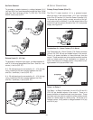
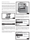

ƽ CONNECTING THE CONTROL
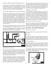
Make sure all power to the devices and terminal blocks is
off, and remove any remaining jumpers from the terminals.
Reconnect the terminal blocks to the control by carefully
aligning them with their respective headers on the control,
and then pushing the terminal blocks into the headers. The
terminal blocks should snap firmly into place, see Figure 41.
Install the supplied safety dividers between the unpowered
sensor inputs and the powered or 115 V (ac) wiring cham-
bers.
Apply power to the control. The operation of the control on
power up is described in the Sequence of Operation section
of this instruction manual.
CLEANING THE CONTROL
The control’s exterior can be cleaned using a damp cloth.
Moisten the cloth with water and wring out prior to wiping
the control. Do not use solvents or cleaning solutions.
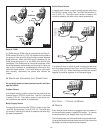
GENERAL
The DIP switch settings on the control are very important
and should be set to the appropriate settings prior to mak-
ing any adjustments to the control through the User
Interface. The DIP switch settings change the items that are
available to be viewed and / or adjusted in the User
Interface.
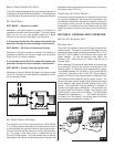
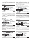
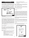
If a DIP switch is changed while the control is powered up,
the control responds to the change in setting by returning
the display to the VIEW menu, see Figure 42.
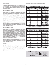
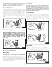
EXTERNAL INPUT / STAND ALONE
The External Input / Stand Alone DIP switch selects whether
a Lochinvar Outdoor Sensor TST2311 or an external 0 - 10
V (dc) input signal is to be connected to the Com - and the
Out + terminals (1 and 4) (FIG. 43).
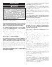
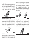
ADVANCED / INSTALLER
The Adv / Installer DIP switch selects the access level of the
control (FIG. 44). In the Installer access level, a limited
number of items may be viewed and / or adjusted. In the
Advanced access level, all items may be viewed and / or
adjusted.
ALARM / COMBUSTION AIR
FIG. 41
22
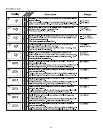
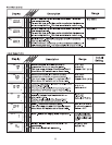
DIP SWITCH SETTINGS
TM
FIG. 42
FIG. 43
FIG. 44