


STEP ONE ----- GETTING READY
Check the contents of this package. If any of the contents
listed are missing or damaged, please contact your whole-
saler or Lochinvar sales representative for assistance.
MP
2
includes: One Boiler Control MP
2
, One Outdoor Sensor
TST2311, Two Temperature Sensors TST2313, Instruction
Manuals INS7141 and INS7162
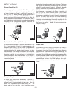
Note: Carefully read the details of the Sequence of
Operation to ensure that you have chosen the proper con-
trol for your application.
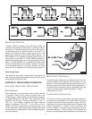
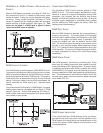
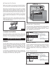
ƽ STEP TWO ---- ROUGH-IN WIRING
All electrical wiring terminates in the control base wiring
chamber. The base has standard 7/8" (22 mm) knockouts
which accept common wiring hardware and conduit fittings.
Before removing the knockouts, check the wiring diagram
and select those sections of the chamber with common volt-
ages. Do not allow the wiring to cross between sections as
the wires will interfere with safety dividers which should be
installed at a later time.
Power must not be applied to any of the wires during
the rough-in wiring stage.
• All wires are to be stripped to a length of 3/8" (9 mm) to
ensure proper connection to the control.
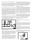
• If an Outdoor Sensor TST2311 is used, install the sensor
according to the installation instructions in the INS7141 and
run the wiring back to the control.
• Install the TST2311 sensor according to the installation
instructions in the Data Brochure D 070 and run the wiring
back to the control.
• If a TST2311 sensor is used, install the sensor according
to the installation instructions in the Data Brochure D 070
and run the wiring back to the control.
• Run wire from other system components (pumps, boilers,
etc.) to the control.
• Run wires from the 115 V (ac) power to the control. Use a
clean power source with a 15 A circuit to ensure proper
operation. Multi-strand 16 AWG wire is recommended for
all 115 V (ac) wiring due to its superior flexibility and ease of
installation into the terminals.
STEP T
HREE ----- ELECTRICAL CONNECTIONS TO THE
CONTROL
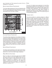
General
The installer should test to confirm that no voltage is pres-
ent at any of the wires. Push the control into the base and
slide it down until it snaps firmly into place.
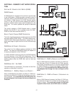
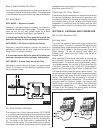
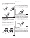
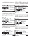
POWERED INPUT CONNECTIONS
115 V (ac) Power
Connect the 115 V (ac) power supply to the Power L and
Power N terminals (10 and 9) (FIG. 26). This connection
provides power to the microprocessor and display of the
control. As well, this connection provides power to the Prim
P1 terminal (11) from the Power L terminal (10).
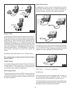
Boiler Demand
To generate a boiler demand, a voltage between 24 V (ac)
and 230 V (ac) must be applied across the Boil Dem and
Com Dem terminals (6 and 7) (FIG. 26).
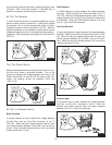
DHW Demand
To generate a DHW Demand, a voltage between 24 V (ac)
and 230 V (ac) must be applied across the Setp / DHW and
Com Dem terminals (8 and 7) (FIG. 26). If using DHW, the
last boiler in MODE 1, 4 or 5 must be set to OFF and DHW
MODE must also be set to 1 through 4.
ƽƽ
CAUTION
Improper installation and operation of this control could
result in damage to the equipment and possibly even
personal injury. It is your responsibility to ensure that this
control is safely installed according to all applicable
codes and standards. This electronic control is not
intended for uses as a primary limit control. Other con-
trols that are intended and certified as safety limits must
be placed into the control circuit. Do not open the con-
trol. Refer to qualified personnel for servicing. Opening
voids warranty and could result in damage to the equip-
ment and possibly even personal injury.
INSTALLATION
17