


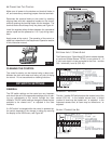
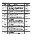
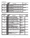
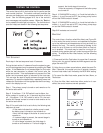

The control has a built-in test routine that is used to test the
main control functions. The control continually monitors the
sensors and displays an error message whenever a fault is
found. See the following pages for a list of the control’s
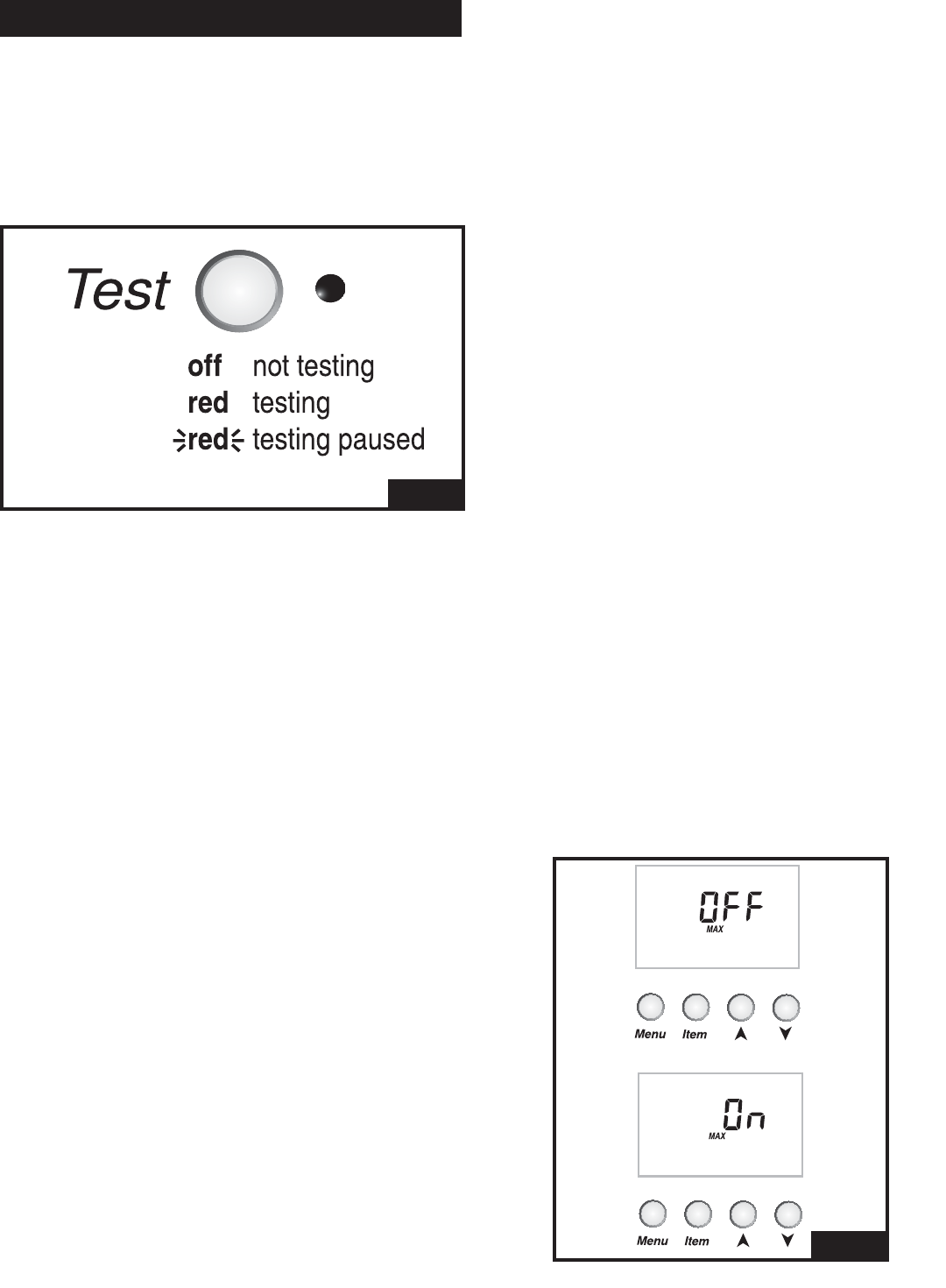
error messages and possible causes. When the Test but-
ton is pressed, the test light is turned on. The individual out-
puts and relays are tested in the following test sequence.
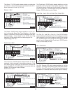
TEST SEQUENCE
Each step in the test sequence lasts 10 seconds.
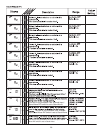
During the test routine, if a demand from the system is pres-
ent, the test sequence may be paused by pressing the Test
button. If the Test button is not pressed again for 5 minutes
while the test sequence is paused, the control exits the
entire test routine. If the test sequence is paused, the Test
button can be pressed again to advance to the next step.
This can also be used to rapidly advance through the test
sequence. To reach the desired step, repeatedly press and
release the Test button until the appropriate device and seg-
ment in the display turn on.
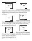
Step 1 The primary pump is turned on and remains on for
the entire test routine.
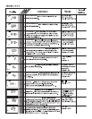
Step 2 If the Alarm / C.A. DIP switch is set to Alarm, the
Alarm contact is turned on for 10 seconds and then shuts
off. If the Alarm / C.A. DIP switch is set to C.A, the com-
bustion Air Damper contact is turned on and remains on for
the entire test routine.
Step 3 For each boiler that is set to Auto, the following test
sequence is used.
• If the mode indicates that a boiler pump is used,
the boiler pump is turned on and remains on.
• Next, the first stage of the boiler is turned on and
remains on.
• If a second stage is present, the second stage is
turned on and remains on.
• If a third stage is present, the third stage is
turned on and remains on. If a fourth stage is
present, the fourth stage is turned on.
• After ten seconds, all stages and the boiler pump
are turned off.
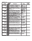
Step 4 If DHW MODE is set to 1 or 2 and the last boiler in
modes 1, 4, and 5 are set to OFF, the primary pump is shut
off and the DHW contact is closed.
Step 5 If DHW MODE is set to 3 or 4 and the last boiler in
modes 1, 4, and 5 are set to OFF, the primary pump stays
on and the DHW contact is closed.
Step 6 All contacts are turned off.
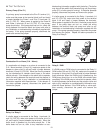
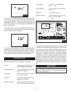
MAX HEAT
The control has a function called Max Heat, see Figure 52.
In this mode, the control turns on and operates the system
up to the maximum set temperatures as long as there is a
demand for heat. The control continues to operate in this
mode for up to 24 hours or until the Item, Menu or Test but-
ton is pressed. This mode may be used for running all cir-
culators during system start-up in order to purge air from the
piping. To enable the Max Heat feature, use the following
procedure.
1) Press and hold the Test button for more than 3 seconds.
At this point, the control flashes the MAX segment and dis-
plays the word OFF.
2) Using the up or down arrow buttons, select the word On.
After 3 seconds, the control turns on all outputs. However,
the max heat mode is still limited by the BOIL MAX setting.
3) To cancel the Max Heat mode, press the Item, Menu, or
Test button.
4) Once the Max Heat mode has either ended or is can-
celled, the control resumes normal operation.
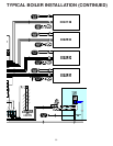
FIG. 51
FIG. 52
29
TESTING THE CONTROL