


INSTALLATION
Continued
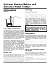
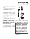
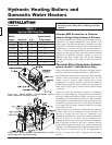
Water heater models do not have downstream test valves, but
the rest of the gas train is represented by Figure 19.
Combination Gas Valves
These units fire in up to 2 stages of burner input. Each stage of
burner operation has a combination gas valve or series of gas
valves to cycle the gas supply on and off and regulate gas to the
burners. Each combination valve consists of a gas regulator and
two valve seats to meet the requirements for redundant gas
valves. The valve has a gas control knob that must remain in the
open position at all times when the unit is in service. The gas
control valve has pressure taps located on the inlet and discharge
sides of the valve. Manifold pressure is adjusted using the
regulator located on the valve. A manifold gas pressure tap for
each burner stage is located on the discharge side of the valve.
The manifold pressure is preset at the factory and adjustment
is not usually required. If you must adjust regulator pressure,
follow the instructions under Gas Manifold Pressure
Adjustment, page 19.
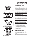
Venting of Combination Gas Valves
The combination gas valve/regulator used on all units is
equipped with an integral vent limiting orifice per ANSI
Z21.78. The vent limiter ensures that the volume of gas
emitted from the valve does not exceed the maximum safe
leakage rate allowed by agency requirements. Combination
gas valve/regulators equipped with integral vent limiters are
not required to have vent or relief lines piped to the outdoors.
The termination of the vent limited opening on the
combination gas valve/regulator complies with the safety code
requirements of CSD-1, CF-190(a) as shipped from the
appliance manufacturer without the installation of additional
vent lines.
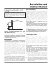
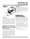
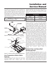
Checking Gas Supply Pressure
Use the following procedure to check gas supply pressure.
1. Turn the main power switch to the "OFF" position.
2. Turn gas valve knobs to the "OFF" position.
3. Shut off gas supply at the field-installed manual gas cock
in the gas piping to the unit. If fuel supply is L.P. gas, shut
off gas supply at the tank.
4. Remove the 1/8" hex plug, located on “inlet” side of the
gas valve. You may also use a tapping on the field-installed
main manual gas cock or gas piping. Install a fitting in the
inlet pressure tapping suitable to connect to a manometer
or magnahelic gauge. Range of scale should be 14" w.c. or
greater to check inlet pressure.
5. Turn on gas supply at the manual gas cock, turn on L.P. gas
at tank if required.
6. Turn the power switch to the “ON” position.
7. Turn the gas valve knobs to the “ON” position. Set the
electronic temperature control or thermostat to call for
heat.
8. Observe the gas supply pressure as all burners are firing.
Ensure that inlet pressure is within the specified range. See
Connecting To Gas Supply, page 16 for minimum and
maximum gas supply pressures.
Hydronic Heating Boilers and
Domestic Water Heaters
18
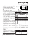
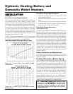
Nominal Iron Length of Pipe In Straight Feet
Pipe Size,
(Inches) 10 20 30 40 50 60 70 80 90 100 125 150 175 200
TABLE - H
Multiple Unit Installations Gas Supply Pipe Sizing
3/4" 369 256 205 174 155 141 128 121 113 106 95 86 79 74
1" 697 477 384 328 292 267 246 226 210 200 179 164 149 138
1 1/4" 1,400 974 789 677 595 543 502 472 441 410 369 333 308 287
1 1/2" 2,150 1,500 1,210 1,020 923 830 769 707 666 636 564 513 472 441
2" 4,100 2,820 2,260 1,950 1,720 1,560 1,440 1,330 1,250 1,180 1,100 974 871 820
2-1/2" 6,460 4,460 3,610 3,100 2,720 2,460 2,310 2,100 2,000 1,900 1,700 1,540 1,400 1,300
3" 11,200 7,900 6,400 5,400 4,870 4,410 4,000 3,800 3,540 3,300 3,000 2,720 2,500 2,340
4" 23,500 16,100 13,100 11,100 10,000 9,000 8,300 7,690 7,380 6,870 6,150 5,640 5,130 4,720
Maximum capacity of pipe in thousands of BTU’s per hour for gas pressures of 14 Inches Water Column (0.5 PSIG) or less and a total system
pressure drop of 0.5 Inch Water Column (Based on NAT GAS, 1025 BTU’s per Cubic Foot of Gas and 0.60 Specific Gravity).