


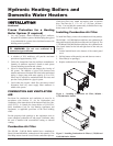

INSTALLATION
Continued
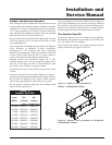
Input Flue
Btu/hr Size
495,000 6"
645,000 8"
745,000 8"
985,000 10"
1,255,000 12"
1,435,000 12"
1,795,000 14"
2,065,000 14"
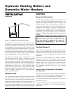
Vent System Options
This unit has two venting options.
1. Conventional Negative Draft Venting
This option uses a vertical rooftop flue termination.
Combustion air is supplied from the mechanical room. See
page 13 for detailed information.
2. Outdoor Installation Venting
This option uses the installation of special air inlet and vent
caps on the unit. See page 13 for venting details.
All units are shipped from the factory equipped for
conventional negative draft venting. All other optional vent
systems require the installation of specific vent kits and
venting materials. The following is a detailed explanation of
the installation requirements for each venting system,
components used and part numbers of vent kits for each model.
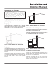
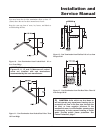
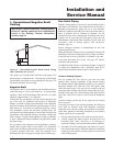
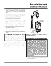
Barometric Damper Location
Any venting system option that requires a barometric damper
must adhere to the following directions for optimum
performance.
The preferred location for the barometric damper is in a tee or
collar installed in the vertical pipe rising from the unit’s flue
outlet. The barometric damper MUST NOT be installed in a
bull head tee installed on the unit’s flue outlet. The tee or collar
containing the barometric damper should be approximately
three feet vertically above the connection to the unit’s flue
outlet. This location ensures that any positive velocity pressure
from the unit’s internal combustion fan is dissipated and the
flue products are rising due to buoyancy generated from the
temperature of the flue products. Adjust weights on damper to
ensure that draft is maintained within the specified ranges.
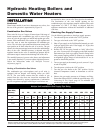
Hydronic Heating Boilers and
Domestic Water Heaters
12
TABLE - B
Flue Pipe Sizes
TABLE–C
Minimum Recommended Combustion Air Supply To Boiler Room
Combustion Air Source
Boiler Input Outside Air*/2 Openings Outside Air*/1 Opening Inside Air/2 Openings
495,000 125 in
2
(806 cm
2
) 167 in
2
(1077 cm
2
) 500 in
2
(3226 cm
2
)
645,000 163 in
2
(1052 cm
2
) 217 in
2
(1400 cm
2
) 650 in
2
(4194 cm
2
)
745,000 188 in
2
(1213 cm
2
) 250 in
2
(1613 cm
2
) 750 in
2
(4839 cm
2
)
985,000 248 in
2
(1,600cm
2
) 330 in
2
(2,129cm
2
) 990 in
2
(6,388cm
2
)
1,255,000 315 in
2
(2,032cm
2
) 420 in
2
(2,710cm
2
) 1260 in
2
(8,130cm
2
)
1,435,000 360 in
2
(2,323cm
2
) 480 in
2
(3,097cm
2
) 1440 in
2
(9,291cm
2
)
1,795,000 450 in
2
(2,903cm
2
) 600 in
2
(3,871cm
2
) 1800 in
2
(11,614cm
2
)
2,065,000 518 in
2
(3,342cm
2
) 690 in
2
(4,452cm
2
) 2070 in
2
(13,356cm
2
)
*Outside air openings shall directly communicate with the outdoors. When combustion air is drawn from the outside through a duct, the net free area of each of the two openings
must have twice (2 times) the free area required for Outside Air/2 Openings. The above requirements are for the boiler only, additional gas fired units in the boiler room will require
an increase in the net free area to supply adequate combustion air for all units. Combustion air requirements are based on the latest edition of the National Fuel Gas Code, ANSI
Z223.1, in Canada refer to CAN/CGA-B149 Installation Code. Check all local code requirements for combustion air.