


INSTALLATION
Continued
Circulator Pump Requirements
This is a low mass, high efficiency hot water boiler which must
have adequate flow for quiet, efficient operation. Pump
selection is critical to achieve proper operation. A pump should
be selected to achieve proper system design water temperature
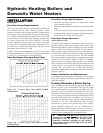
rise. Two heat exchanger head-loss charts (Figure 25A & 25B)
are provided to assist in proper pump selection. Also provided
is a System Temperature Rise Chart (TABLE-K). This table
provides GPM and boiler head-loss at various temperature
rises for each boiler based on Btu/hr input. Temperature rise is
the difference in boiler inlet temperature and boiler outlet
temperature while the boiler is firing.
Example: The boiler inlet temperature is 160°F (71°C) and the
boiler outlet temperature is 180°F (82°C), this means that there
is a 20°F (11°C) temperature rise across the boiler.
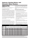
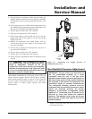
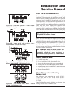
Heat Exchanger Pressure Drop Chart
Figure 25A - Pressure Drop Chart_Models 495,000 -
745,000 Btu/hr
Figure 25B - Pressure Drop Chart_Models 985,000 -
2,065,000 Btu/hr
Circulator Pump Specifications
1. Maximum operating pressure for pump must exceed
system operating pressure.
2. Maximum water temperature should not exceed nameplate
rating.
3. Cast iron circulators may be used for closed loop systems.
4. A properly sized expansion tank must be installed near the
boiler and on the suction side of the pump.
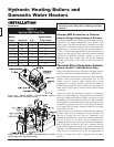
Circulator Pump Operation
(Heating Boilers Only)
The boiler pump should run continuously unless the boiler is
provided with the optional pump delay control system. This
optional pump control system is available as a factory-installed
option. External wire leads are furnished with this option to
allow the power supply for the pump to be switched across the
normally open contacts of the relay, allowing the control relay
to cycle the pump on each call for heat. The field installed
boiler pump (using the optional factory supplied pump control
system) must not exceed 10 AMPS at 120VAC. As shipped
from the factory, the optional control system is set to cycle the
boiler pump on at each call for heat before the burners fire and
run the pump for a 30 second period after the thermostat is
satisfied. This will remove any residual heat from the
combustion chamber before turning the pump off. See Wiring
Diagrams, page 47.
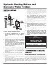
Pump Installation and Maintenance
For installation and maintenance information on the circulator
pump, refer to pump manufacturers instructions included in the
instruction package.
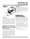
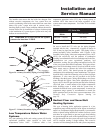
Primary/Secondary Boiler Piping
Boiler installations with a primary/secondary piping system as
shown in Figure 26 are recommended. This type of system
uses a dedicated pump to supply flow to the boiler only. This
secondary pump is sized based on desired boiler flow rate,
boiler head loss and head loss in the secondary system piping
only. A properly-sized system pump provides adequate flow to
carry the heated boiler water to radiation, air over coils, etc.
The points of connection to the primary system should be a
maximum of 12" (or 4 pipe diameters) apart to ensure
connection at a point of zero pressure drop in the primary
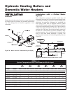
system. Multiple boilers may also be installed with a
primary/secondary manifold system as shown in Figure 27.
The multiple boilers are connected to the manifold in reverse
return to assist in balancing flow to multiple boilers.
ƽ CAUTION: DO NOT allow the flow in the
primary loop to drop lower than the flow in the
secondary loop at any time during boiler
operation. Improper operation of the boiler(s)
and possible tripping of the high limits and relief
valves may occur.
Hydronic Heating Boilers and
Domestic Water Heaters
24