52
This appliance uses a single cylindrical burner installed vertically
into the cavity located in the center of the primary heat
exchanger. There is a unique burner for each one of the three
models.
Burners may NOT be changed between different Btu/hr input
models. The burner consists of a round mounting flange welded
to a mixing tube. The top side of the mixing tube provides the
transition which mounts the discharge from the combustion air
blower into the burner. The bottom side of the mixing tube is
attached to a stainless steel perforated sleeve. This stainless steel
sleeve is covered with a loose fitting, woven alloy
ma te ri al that forms the burner port sur face. The woven burner
port material is called Alcromesh which is a unique alloy of iron,
chrome, aluminum and several rare earth metals. This alloy is
designed to operate stress free as a burner port surface. The
Alcromesh burner port surface can sustain op er a tion from a blue
flame down to infrared conditions as the burner input varies.
Internally, the burner has a cone and distribution baffles to
balance the air/gas mixture over the surface of the burner. The
burner mounting flange provides a flame view port and the
mounting point for the hot surface igniter. The hot surface igniter
is removable from the burner mounting flange without removing
the burner assembly from the heat exchanger.
NOTE:
An index mark is provided on the burner flange to ensure
proper ori en ta tion when removing and reinstalling the
burner. A properly indexed burner will ensure correct
location of the com bus tion air blower and adequate
clearances from other components in the top jacket
chamber.
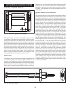
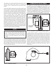
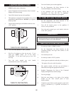
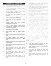
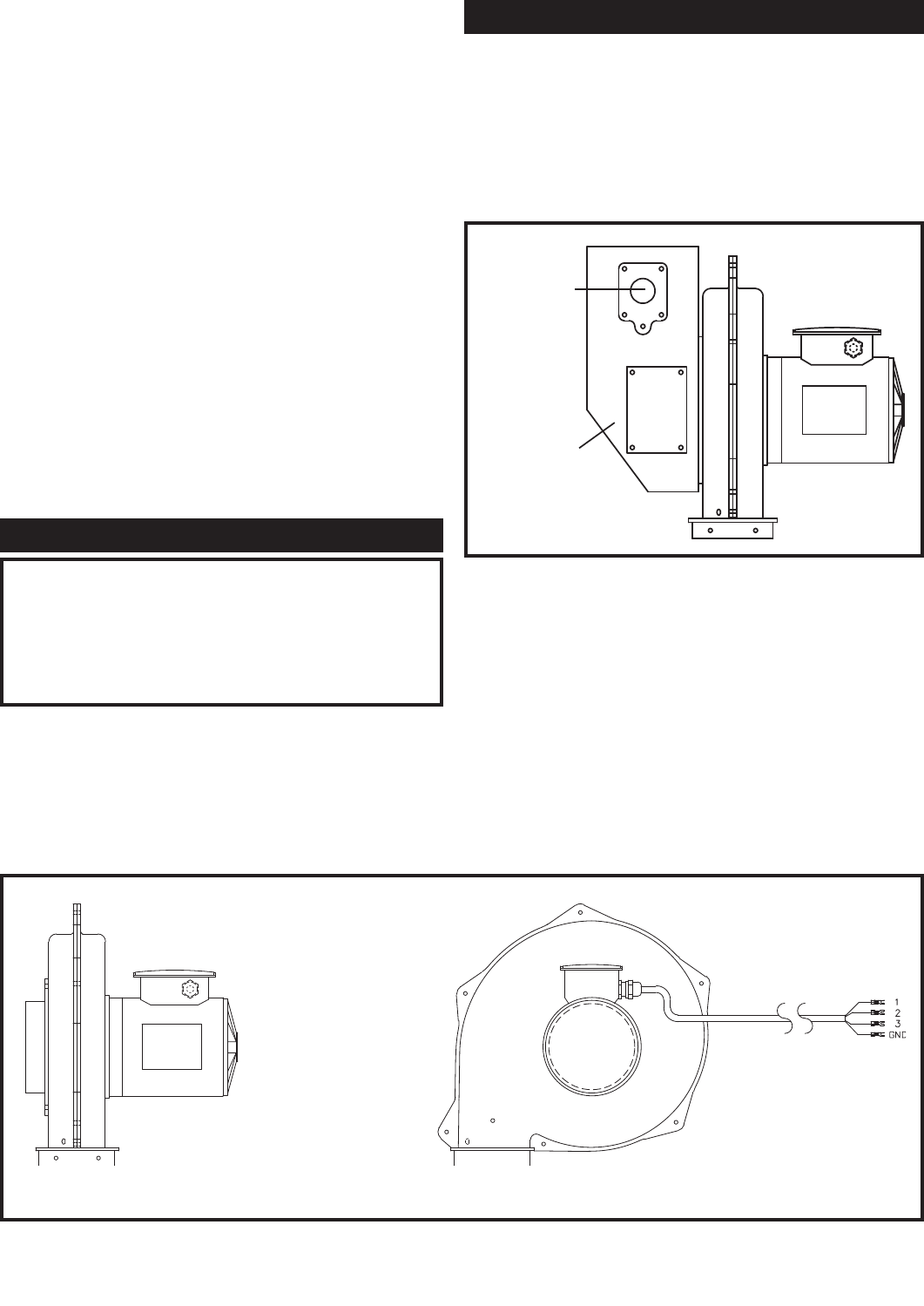
FIG. 68 Combustion Air Blower
The burner is designed to operate from 100% of rated input down
to 25% of rated input in normal operation. Burn er operation at
input rates of less than 50% may include operation in the infrared
state. At input rates firing above 50%, there may be some slight
infrared visible on the tips of the woven burner port material.
This is normal burner operation.
COMBUSTION AIR BLOWER
ORIFICE
MOUNTING
TRANSITION
CHAMBER
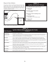
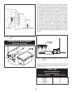
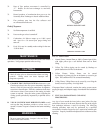
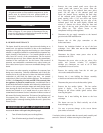
FIG. 69 Combustion Air Blower and Transition Chamber
A sealed transition chamber is mounted on the inlet to the
combustion air blower. This chamber contains the gas orifice and
a sensing point for op er a tion of the ratio gas valve. Inside the
transition chamber, at the inlet to the combustion air blower there
is a filter to prevent particulate matter and small foreign objects
from entering the blower and burner. This filter should be checked
and cleaned on a six month interval or more often in a con tam inated
environment. An inspection port is provided on the side of the
transition chamber to allow access to the internal filter for
inspection and cleaning. If cleaning is required, remove the filter
through the inspection port and clean with soapy water or
compressed air.
This appliance uses a sealed air blower to provide combustion air
for the burn er and operate the Category IV venting system. The
blower assembly consists of a sealed housing and blower wheel
constructed from cast aluminum. The blower is operated by a fully
en closed 230 VAC, 3 Phase electric motor. This motor has a 3/4 HP
rating on the 1,500,000 Btu/hr model and a 1 HP rat ing on the
1,700,000 and 2,000,000 Btu/hr models. The blower housing and
motor assembly is fully sealed and CANNOT be field serviced.


