


PAGE 15
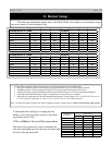
BIASI B/40
All piping must conform to state and local codes.
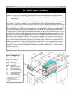
The supply and return manifolds for B-40 Linear boilers are 2 1/2” male NPT. Be sure to
provide unions and gate valves at the manifold inlet and outlet of the boiler, so the boiler may be
readily isolated for service.
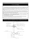
Install the provided pressure relief valve so the discharge is piped directly to a drain, if
possible. If not, the discharge should be piped to the floor. In either case, the discharge pipe should be
of the same diameter as the outlet of the relief valve, with no valves or obstructions to impede
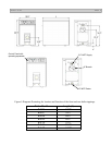
overflow from the boiler. The installation locations on the manifold for the Pressure Relief Valve, the
Temperature/Pressure Gauge as well the Honeywell L4006E Aquastat can be seen on the following
page.
Install manual and/or automatic air venting devices at the high points in the system to eliminate
trapped air.
The weight of all piping should be supported by suitable hangars and floor stands, not by the
boiler.
It is recommended that the make-up water line have a backflow preventer and a pressure-
reducing valve to reduce line pressure to 10 to 15 psi installed adjacent to the boiler.
NOTE: If the heating system is to be filled with antifreeze, use only formulations expressly made for
hydronic heating systems (such as propylene glycol). Do not use automotive types of antifreeze
(ethylene glycol). Use of antifreeze will alter system output and characteristics. Consult factory rep's
for details or assistance.
Clearance for hot water pipes are 1 inch to combustibles.
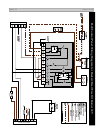
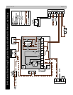
11. Piping:
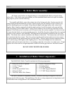
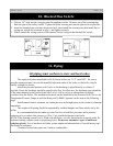
1. Pierce a 5/8” hole into the vent pipe near the appliance outlet. Remove one of the securing nuts
from the pipe of the safety switch. Tighten the other securing nut onto the pipe as far as possible.
2. Insert the threaded pipe end into the pierced hole, then install the securing nut, then install the se-
curing nut, which was removed in step 1, and tighten securely.
3. Please consult the wiring section of this manual for the wiring of the blocked flue switch.
10. Blocked Flue Switch: