


BIASI B/40
PAGE 12
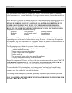
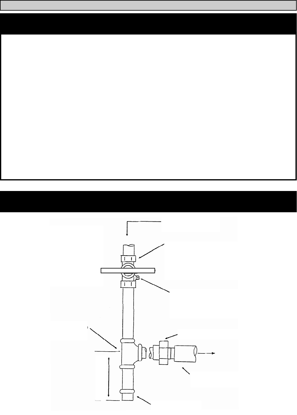
To check for
gas leaks, use
a gas detector
or apply a
soap solution
to the joints.
DO NOT USE AN
Direction of
flow
Manual Shutoff Valve
Height of shutoff valve
above ground level to
conform to local codes,
Pressure Gauge
Port
(1/8” NPT plugged)
Minimum
1” X 1” X 1” Tee
Male Union 1” NPT
Burner Gas
Pipe Cap
3” MINIMUM
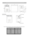
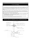
INSTALLATION OF SEDIMENT TRAP AND BURNER SUPPLY
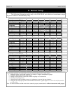
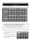
Gas supply piping is to be sized and installed properly in order to provide a supply of gas sufficient
to meet the maximum demand without undue loss of pressure between the meter and the boiler. It is
advisable to run a separate gas line from the meter to the gas burner to avoid pressure drops. Consult
with the National Fuel Gas Code ANSI Z223.1 for proper sizing of gas piping for various lengths and
diameters.
Locate a drop pipe adjacent to, but not in front of the boiler. Locate a tee in the drop pipe at the
same elevation as the gas inlet connection to the boiler. Extend the drop line with a nipple towards the
floor and cap to form a sediment trap. Install a tee handle shut off valve before the tee with sediment
trap and a union after the tee before the combination gas valve.
When installing the boiler, Use black steel pipe and malleable fittings (do not use cast iron parts) with
a suitable pipe dope which is resistant to liquefied petroleum gases.
Check piping for leaks. Always check leaks with a water and soap solution. DO NOT USE A
FLAME FOR CHECKING GAS LEAKS
The boiler and its individual shut-off valve must be disconnected from the gas supply piping
during any pressure testing of that piping at test pressures in excess of 1/2 psi.
9. Gas Line Piping