


Prince XL
®
- Owner's Manual - Page 7
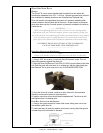
DRIVE AND IDLER ROLLS
GENERAL
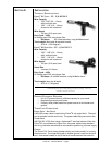
The Prince
®
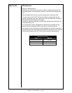
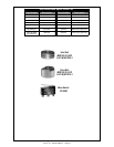
XL torch comes standard with knurled drive rolls which will
handle wire diameters from .023 - 1/16 inch. Optional grooved drive rolls are
also available for feeding aluminum wire if desired (see Optional kits).
Drive roll tension is accomplished by means of a pressure adjusting allen
screw located on the left hand side of the torch. Proper tension is achieved
when wire does not slip if a small amount of pressure is added to the wire as
it exits the tip.
----------- IMPORTANT -----------
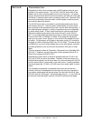
NOTE: Over-tightening of the drive rolls will cause excessive knurling and/or
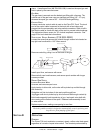
deformation of the wire. When the complete system is setup properly, feeding wire
out of the end of the torch and letting fall on the ground should form a large uniform
circle. If it forms a spiral or spring then there is too much tension in the system,
please refer to the Cabinet Owners Manual for adjustment to the tension setting.
INCORRECT DRIVE ROLL TENSION IS THE NUMBER ONE
CAUSE OF POOR WIRE FEED PERFORMANCE
---------------------------------------------
D
RIVE ROLL INSTALLATION AND REMOVAL
Note:
Neither of the handles needs to be removed to access the Drive or Idler Rolls.
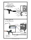
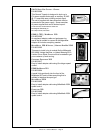
1. Using a 5/32” hex wrench, loosen the Idler Roll tension screw. This will
relieve the pressure against the drive roll.
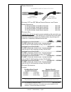
2. Align the Drive Roll Removal Tool (P/N 931-0100) over the fl ats of the drive
roll. Hold the torch with one hand or on a table top, with the other hand give
the Removal Tool a quick snap-turn in the CLOCKWISE DIRECTION.
3. Once the drive roll is loose, continue to spin drive roll in the clockwise
direction to remove the drive roll from the torch.
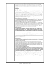
4. Install a new drive roll on the left-hand threaded shaft. The drive roll will
self-tighten when it is feeding wire.
I
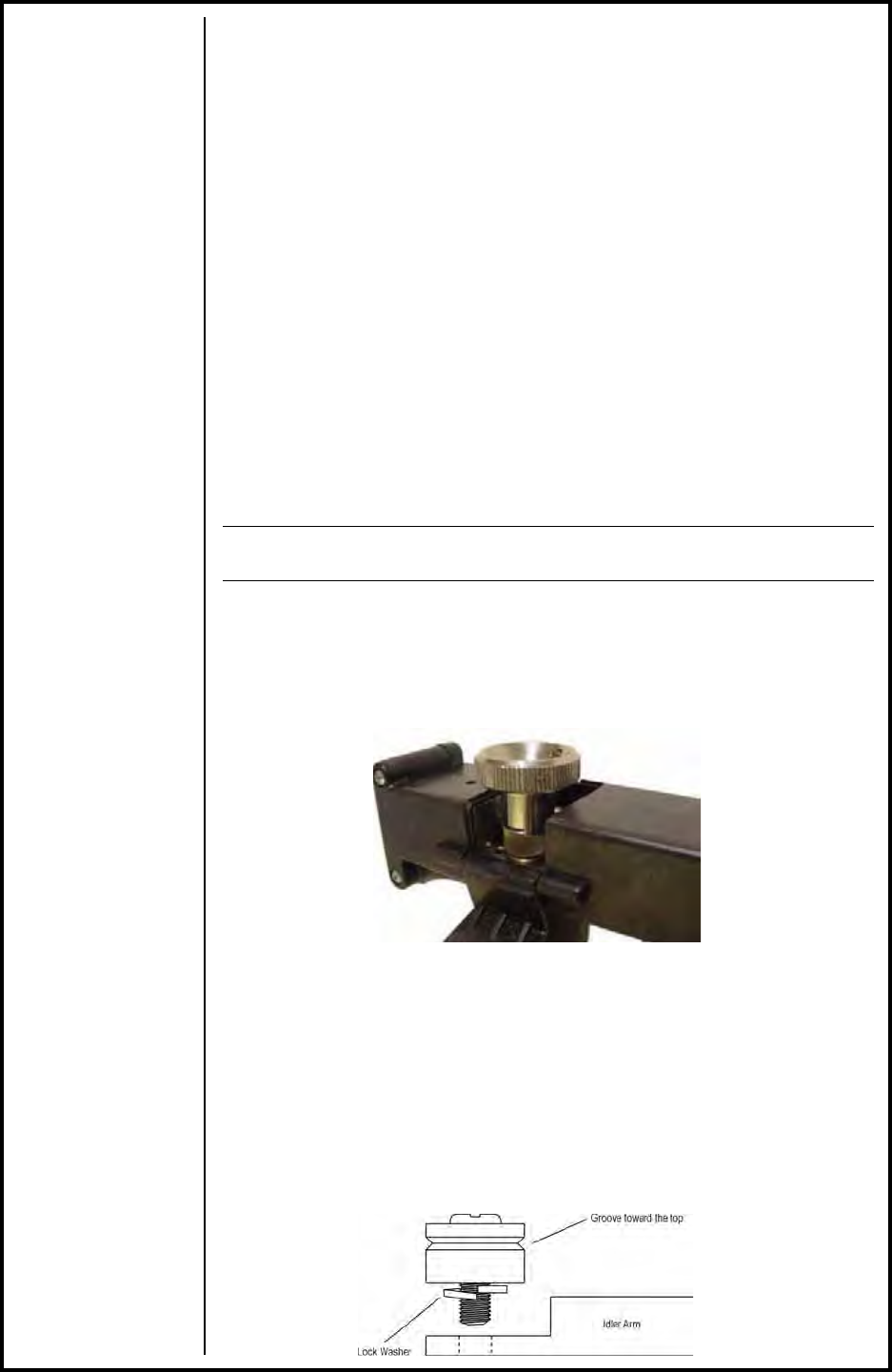
DLER ROLL INSTALLATION AND REMOVAL
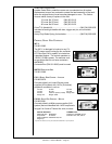
1. Using a slot type screwdriver, loosen idler screw, taking care not to lose
lock washer under idler roll.
2. Insert new idler roll and lock washer onto screw, insuring that idler groove
is toward top and lock washer is beneath.