


Prince XL
®
- Owner's Manual - Page 6
the slave motor in the cabinet, combined with the pull of the torch motor,
causes the wire to literally fl oat friction-free through the wire conduit. The
24VDC torch motor is controlled by a 3-3/4 turn potentiometer in the torch
handle.
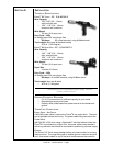
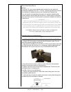
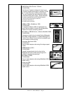
BARRELS
AIR/WATER COOLED
The Prince® XL air cooled systems come standard with a straight air/water
cooled barrel assembly. An optional curved air/water cooled barrel assembly
(LE P/N KP2298-2, MK P/N 003-2152) is also available. In cases where
these barrels need to be extended or the tip threads have been damaged,
a Tip Extender (LE P/N KP2244-1, MK P/N 621-0424) can be adapted. The
same tips and threads can be used, however a longer Tefl on liner (LE P/N
KP2226-1; MK P/N 931-0137) is required.
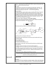
B
ARREL REMOVAL AND INSTALLATION
To remove a barrel assembly, loosen the patented EZ Lock™ Taper lock nut
assy MK P/N 003-2572 3/4 to 1 turn. This will push barrel away from the
body far enough so that it may be pulled out of the body.
To replace a barrel assembly, take care not to damage the “O” rings when
inserting into the body. Open the drive and idler roll door and seat the barrel
assembly until the inlet guide is almost touching the drive and idler roll and
the rear face of the barrel is fl ush with the aluminum body block. Tighten
taper lock nut assembly fi rmly so that barrel cannot rotate.
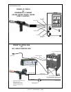
B
ARREL ROTATION
To rotate a barrel assembly, loosen the patented EZ Lock™ Taper lock nut
assembly no more than 1 turn. Rotate barrel to the position of your choice
and retighten taper lock nut assembly fi rmly so that the barrel cannot rotate.
WARNING:
Do not attempt to weld without the barrel being tightly secured in the torch body, or
damage to the barrel or body may result.
CONTROLS AND SETTINGS
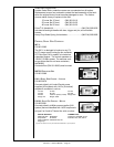
POTENTIOMETER
The pot is located in the bottom of the pistol grip and provides 3-3/4 turns of
rotation and up to 750 ipm.
The pot is mounted to one side of a PC board and is held in place by a
support plate; both of which have slots that locate and secure the pot in the
handles. The other side of the PC board houses the motor connectors and
ribbon cable. Locking disks behind the pot knob provides a stop at the mini-
mum and maximum pot settings.
T
RIGGER, GAS VALVE AND MICRO SWITCH
The torch trigger is designed so that when it is partially depressed, gas fl ow
starts via the valve located in the torch body, prior to ignition of the arc. When
the trigger is partially released after welding (extinguishing the arc), gas fl ow
continues until the trigger is fully released; built-in pre and post gas fl ow.
The micro switch is wired “Normally Open” and secured to the torch block
with two (2) screws. An insulator between the torch block and micro switch
prevents accidental shorting of the switch leads. The trigger pin reaches
through the handle and activates the micro switch just before the trigger bot-
toms out on the handle.