System Operation, Testing, and Maintenance
52
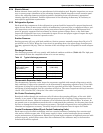
6.2.4 Electric Reheat
Reheat element sheets and fins are manufactured with stainless steel. Regular inspections are neces-
sary to assure proper cleanliness of the reheating element. Should inspection reveal corrosion parti-
cles on the reheating element or adjoining surfaces (including ducts and plenums), appropriate
cleaning should be performed. Periodic replacement of the reheating element may be necessary to
meet specific application requirements.
6.2.5 Refrigeration System
Each month the components of the refrigeration system should be inspected for proper function and
signs of wear. Since in most cases evidence of malfunction is present prior to component failure, peri-
odic inspections can be a major factor in the prevention of most system failures. Refrigerant lines
must be properly supported and not allowed to vibrate against ceilings, floors, or the unit frame.
Inspect all refrigerant lines every six months for signs of wear and proper support. Inspect the capil-
lary and equalizer lines from the expansion valve.
Suction Pressure
Suction pressure will vary with load conditions. Suction pressure normally ranges from 58 psi to 75
psi (405 kPa to 517 kPa). When the 3-ton circuit is operating alone, the upper range of suction pres-
sure may approach 100 psig. This is a function of the unit design and is acceptable for scroll compres-
sors.
Discharge Pressure
The discharge pressure will vary greatly with load and ambient conditions (Table 16). The high-pres-
sure switch will shut the compressor down at its cut-out setting.
Thermostatic Expansion Valve
The thermostatic expansion valve keeps the evaporator supplied with enough refrigerant to satisfy
load conditions. Proper valve operation can be determined by measuring superheat level. If too little
refrigerant is being fed to the evaporator, then the superheat will be high. Conversely, if too much
refrigerant is being supplied, then the superheat will be low. The correct superheat setting is between
10 and 15°F (5.6 and 8.3°C). Only the 5-ton valve is adjustable.
Air-Cooled Condensing Units
Restricted airflow through the condenser coil will reduce the operating efficiency of the unit. Addi-
tionally, it can result in high compressor head pressure and loss of cooling. Using compressed air or
commercial coil cleaner, clean the condenser coil of all debris that will inhibit airflow. In winter, do
not permit snow to accumulate around the side or underneath the condenser. At the same time check
for bent or damaged coil fins and repair as necessary. Check all refrigerant lines and capillaries for
vibration and support as necessary. Carefully inspect all refrigerant lines for signs of oil leaks.
Coaxial Condensers (Water/Glycol-Cooled Condensing Units)
Each water or glycol-cooled condensing unit has a coaxial condenser consisting of an exterior steel
tube and an interior copper tube. If the water supply is clean, coaxial condensers do not normally
require maintenance or replacement. Should your system begin to operate at high head pressure with
reduced capacity, and all other causes have been eliminated, the condenser may be obstructed or
fouled and should be replaced.
Table 16 Typical discharge pressures
System Design psig (kPa)
Air-Cooled 180-275 (1242-1895)
Water-Cooled
65ºF to 85ºF water
(18 to 29.4ºC)
200-225 (1380-1550)
Glycol-Cooled 210-275 (1445-1895)
Maximum 330 (2275)
High Pressure Cut-Out 360 (2480)


