Site Preparation and Installation
16
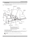
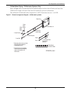
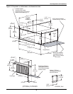
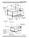
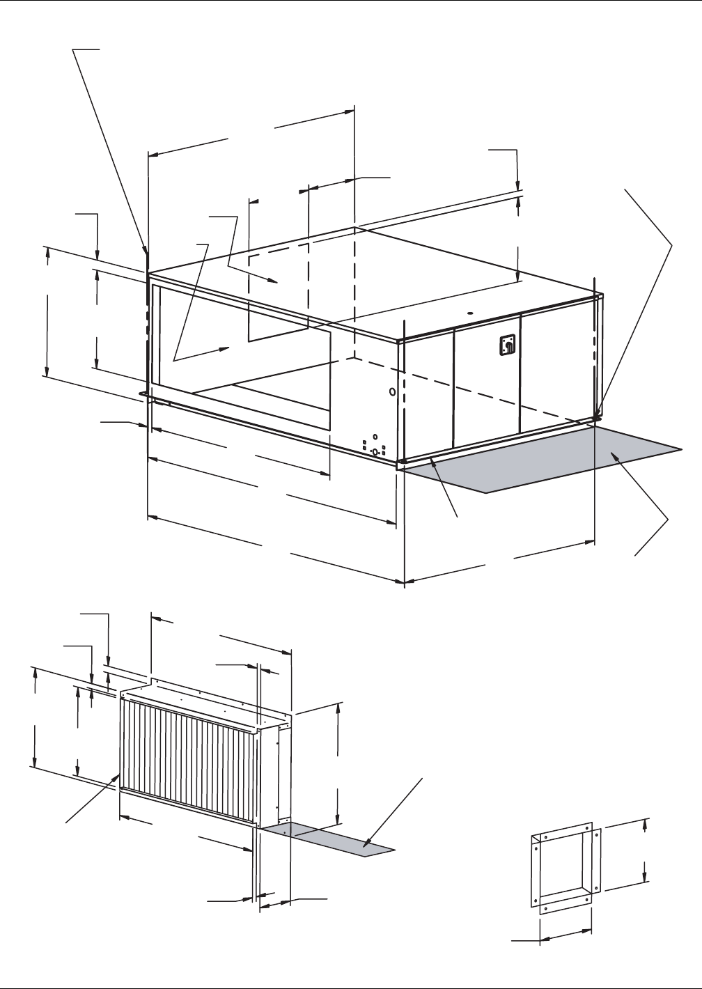
Figure 10 Evaporator or chilled-water unit dimensional data
49 "
21 1/2 "
1"
19 1/2 "
1"
17 1/2 "
8"
1"
47 "
1"
(1244.6mm)
(25.4mm)
(25.4mm)
(25.4mm)
(495.3mm)
(444.5mm)
(1193.8mm)
(25.4mm)
(203mm)
(546.1mm)
Duct Flange
(OPTIONAL) FILTER BOX
54 1/8 "
16 13/16 "
1 3/16 "
1"
50 "
70 "
72 "
50 "
15 5/8 "
12 1/8 "
19 1/2 "
26 1/2 "
16 13/16 "
15 5/8 "
Hanger Bracket
Shaded area indicates a
recommended clearance
of 30" (762mm)
for access
and
filter removal.
9/16" (14mm) dia. holes for
threaded rods (typ. 2 each end)
Customer Supplied
threaded rods for module
support from ceiling (1/2" minimum
diameter recommended) (typ. 4).
Air Outlet
Air Inlet
CABINET
DIMENSION
(1375mm)
(30.2mm)
(308mm)
(397mm)
(427mm)
(1828.8mm)
(1778mm)
(427mm)
(397mm)
(1270mm)
(1270mm)
(25.4mm)
(673mm)
(495mm)
Optional 1" (25.4mm)
Discharge Duct Connection
ships with Filter Box
2"
(50.8mm)
FRONT
OF
UNIT
Shaded area indicates a
recommended clearance
of 30" (762mm)
for access
and
filter removal.
DPN000240_Rev0


