


page 5
English
5 - Operation
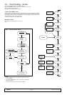
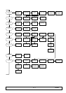
The unit operation is completely automatic.The below
sequence explains (with the assistance of Fig. 5 - OperaĆ
tion diagram) how the unit operates (see also Fig. 6
Refrigerating circuit):
1) The temperature sensor, positioned inside the shelĆ
ter, informs the control about the condition of the air
to be conditioned.
2) The control compares the received information with
the Set Point values (= min. indoor temperature
required) and Differential programmed values, preĆ
setting the air conditioner for the air conditioning
with the following modes:
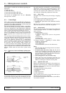
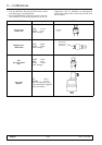
Cooling (Fig. 5)
The compressor (9) and the fans (6) and (10) are started
up when the temperature of the room to be conditioned
exceeds the preset value. The intake air from the centrifĆ
ugal fan (6) enters the unit through the lower gap (A),
goes immediately through the filter (1) and then the
evaporator (5).
The cool refrigerant flows through the evaporator (5),
thus cooling the air passing through it. The conditioned
air is conveyed into the conditioned room through the
discharge opening (B).
The heat taken from the room and the one generated by
the conditioner motor operation are disposed through
the condenser (11) placed in the lower part of the unit
and hit, thanks to the fan (11), by the outside air. The fan
operation is managed in ON - OFF mode (or with
Variex, see par. 5.1) as a function of the condensing presĆ
sure.
For the operation logics of the control see chapter 6.
Heating (optional)
The air heating is achieved by means of electric heaters
(7), located in the air flow and activated according to the
logics set on the control (see chapter 6).
The manual reset of the safety thermostat (15), placed
on the electrical heaters is carried out throught the front
after removing the grill panel.
Cooling in Freecooling (optional) - (Fig. 5)
When the outside air temperature is lower than the
inside air temperature by some degrees, it is possible to
use this difference to refresh the shelter inside part by
direct intake of the outside air, i.e. without using the
compressor. Thus it is possible to achieve a considerable
energy saving.
When the expected conditions occur, the servo-control
(2), managed by the Microface control, opens the movĆ
ing damper (12) separating the flows of the inside air and
outside air. In this way the outside air sucked by the fans
(6) flows inside the container and is discharged through
the openings of the condensing section. The air flows
present in this operation mode are shown in Fig. 5).
The opening degree of the damper is determined as a
function of the set point value to be kept and of the
intake air temperature (see chapter 6).
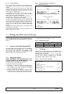
5.1 - Adjustment of the condenser fan speed
(compulsory for outside temperatures
-10_ / -30_C)
A sensor is positioned so as to detect constantly the conĆ
densing pressure of the refrigeration gas. On the basis of
this information, an electronic device (Variex) adjusts
the fan rotation speed in order to keep the condensing
pressure within the allowed values. In this way, besides
optimizing the compressor operation, you can have a
remarkable reduction of the sound pressure level
(mainly during the night), an easier start-up of the comĆ
pressor at low temperatures and some energy saving.
For the calibration of the speed adjuster refer to chapter
8.
5.2 - Emergency cooling
(optional)
This option is available for all those applications where it
is mostly important to guarantee air flow inside the shelĆ
ter, even in the event of mains current drop. In this case,
by an inverter and a transformer, the units can be supĆ
plied by the emergency coils at 24 or 48 V dc (see Fig. 7).
The intervention mode of the emergency system
depends on the switch QS1 condition:
S QS1 = ON
If the main power supply is not cut out, the emerĆ
gency system remains inactive;
if there is no voltage on the main power supply line,
the inverter is automatically activated and, being supĆ
plied by the emergency coils at 24/48 V dc, by the
24/48 V / 230 V transformer it supplies the fan of the
evaporating section and the electronic control. So all
functions of the unit are still managed, allowing the
inside air to recirculate (or the outside air to come in,
if the unit is provided with freecooling) if the temperĆ
ature inside the shelter is not within the permitted
range. In this operation mode, a relay contact (KM6)
signals the activation of the inverter system.
If the voltage of the emergency coils goes below the
safety value, the inverter system is automatically de-
activated.
S QS1 = OFF
In this abnormal condition occurring, for instance,
after a short-circuit in the unit the inverter is autoĆ
matically de-activated.
CAUTION:
For safety reasons do disconnect the automatic switch
QS2 when you want to stop the unit.