


page 4
English
272014 - 04.02.2000
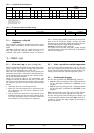
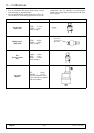
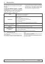
Tab. 3 - Standard electrical features
Evaporator fan Condenser fan Compressor
Heater
(2 x unit)
OA FLA LRA Nom. power
[W]
OA FLA LRA Nom. power
[W]
OA
(*)
FLA LRA Nom. power
[W] (*)
OA FLA LRA Nom. power
[W]
PKS3
1 - - 200 1.5 - - 340 5.9 10 34 1370 - 13 - 3000
PKS4
1 - - 200 1.5 - - 340 7.1 12 36.5 1700 - 13 - 3000
(*) In the following conditions (ARI 520-78):
Condensing temperature 54.4_C,
Ambient temp. 35_C,
Evaporation temp. 7.2_C,
Sub-cooling temp.: 8.3_C
Overheating temp.: 11_C
Tab. 4 - Protection switch and cable sizing
Protection switch with differential current Inn = 0.3A
Cable sizing
V230/1/50Hz 230 Vac 24/48Vdc
PKS3-PKS4
20A
4mm
2
4mm
2
PK
S3
-PK
S4
20A
4
mm
2
4
mm
2
3.2 - Emergency cooling kit
(optional)
The emergency cooling kit consists of an inverter and a
single-phase transformer installed inside the electric
board.
Operating as shown in par. 3.1, supply power up to 48
(24) Vdc inside the electrical panel, by means of a
screened cable with a minimum section as shown in
Tab. 4. Connect the possible ground line to the positive
pole of the 48 Vdc power supply. Connect the cable
screening to the metal cable clamp and perform the conĆ
nections following the wiring diagram carefully.
Attention: Connect the poles correctly.
As regards the units with emergency supply through
external Inverter, make the connections as specified in
the electrical diagram.
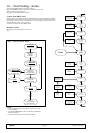
4 - Start-up
4.1 - First start-up (or after a long halt)
Before starting the air conditioner do check if the power
supply voltage and frequency comply with those indiĆ
cated on the identification plate of the unit.
After that, the conditioner can be started putting the
automatic switch QS1 to ON position. On the units proĆ
vided with this switch also press the ON-OFF push butĆ
ton on the Hiromatic interface.
Check the electrical input of all components and
compare it with the data shown in the Tab. 3. Check that
there are no active alarms; wait until the system reaches
the standard operation and then make the following
checks:
S check that the fans are working correctly;
S make sure that the temperature is guaranteed and
the compressor and the heaters (optional) work
when required;
S only on versions provided with the Variex option (speed
adjustment)make sure that the speed adjuster of the
fan of the condensing section is correctly calibrated
and controls the fan operation (see chapter 8).
4.2 - Start-up with low outside temperature
In case of low outside temperature (<0_C), the unit
start-up is helped by the delay time of the low pressure
alarm activation, within which the pressures in the refrigĆ
erating circuit reach the standard operation values.
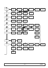
4.3 - Starting and stopping
For the units provided with HIROMATIC interface:
S start the unit by pressing the ON-OFF push button
on the Hiromatic (confirmed by SYS.ON on the
display);
S stop the unit by pressing the ON-OFF push button
on the Hiromatic (confirmed by SYS.OFF. on the
display).
Note: turn the main switch QS1 and the QS2 Inverter
switch off only if the unit is stopped for a long time.
For the units provided with the Microface control, you
can switch on/off using the main switch QS1, which is acĆ
cessible by opening the hinged higher panel acting on
quick lock system.