


—40—
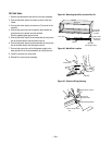
2. To gain access inside the control panel, after removing the
knobs and escutcheon, remove the screws holding panel in
position.
Tilt control panel forward, being careful not to pinch any
wires. (Figure 50)
3. As viewed from the front, remove both knockouts on the
control panel.
4. Insert two fuse holders from the front. The fuse holders
should be oriented so the quick-connect tabs are toward
the center of the unit. Attach fuse holders using the screws
and nuts provided. (Figure 50)
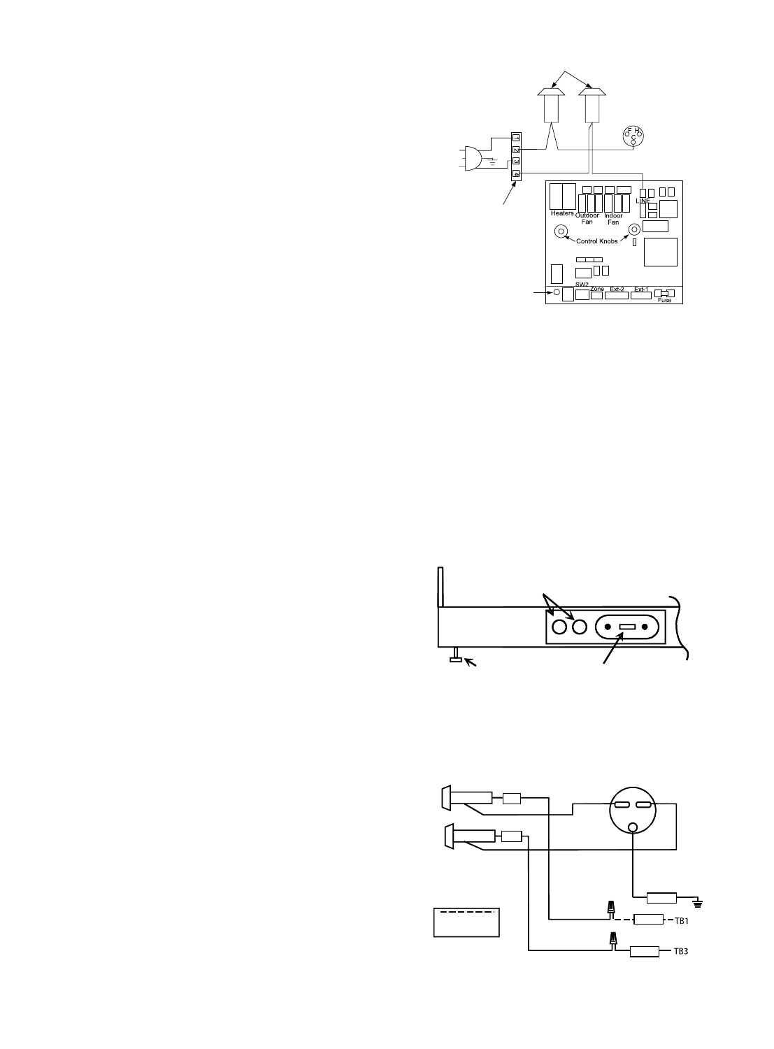
5. Remove both power cord leads, one lead from the
capacitor and one from the electronic board.
6. Install one power cord lead on the center terminal of one
fuse holder. (Figure 51)
7. Install the remaining power cord lead on the center terminal
of the second fuse holder. (Figure 51)
8. Connect BK-10 wire from the side terminal of one fuse
holder to the Line terminal on the electronic board.
(Figure 50)
9. Connect RD-10 wire from the side terminal of the other
fuse holder to the common (C) terminal on the capacitor.
(Figure 51)
10. Tilt control panel back to original location, being careful
not to pinch any wires. Align the control panel with the
cover and screw panels into place with original screws.
Replace escutcheon and control knobs.
Fuse Holder Kit Installation
(With Subbase)
See previous section for installation in the control panel.
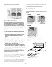
1. Remove both knockouts at the fuse holder location.
(Figure 52)
2. Install the fuse holders using screws provided. The side
connector tab on the fuse holders should be towards the
left.
3. Connect a stripped BK-9 wire to the center of the quick-
connect tab of the fuse holders. Wire nut the other end of
this wire to the black field connection wire (TB1).
(Figure 53)
4. Connect the other stripped BK-9 wire to the quick-connect
tab on the side of the same fuse holder.
Wire nut the other end to black subbase wire leading to
receptacle. (Figure 53)
5. Connect the stripped RD-9 wire to the center quick-connect
tab of the second fuse holder. Wire nut the other end to the
red field connection wire (TB3). (Figure 53)
6. Connect the other stripped RD-9 wire to the quick-connect
tab on the side of the second fuse holder.
Wire nut other end to red subbase wire which leads to
receptacle. (Figure 53)
7. Insert time delay fuses into the fuse holders. Size all fuses
by the Maximum Overcurrent Protection shown on the
nameplate. Also refer to the serial plate on the unit.
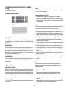
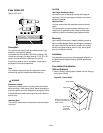
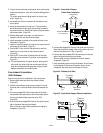
FUSEHOLDERS
Terminal Blocks Behind
the Control Panel
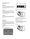
Status Light
Fuse Holder
Knockouts
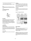
Leveling
Leg
Electrical
Receptacle
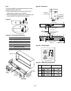
Fuseholder
BK-9
Green
Black
Red
RD-9
Field Connection
Wiring
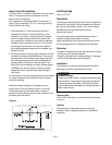
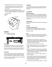
Fuseholder
Power Switch
Knockouts
Control Board
WH
GN
BK
Transformer
Figure 51 - Fuse Holder Diagram
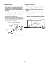
Control Panel Installation
Figure 52 - Subbase (Left Side)
Figure 53 - Fuse Holder Diagram Subbase Installation