


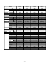
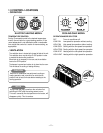
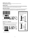
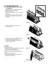
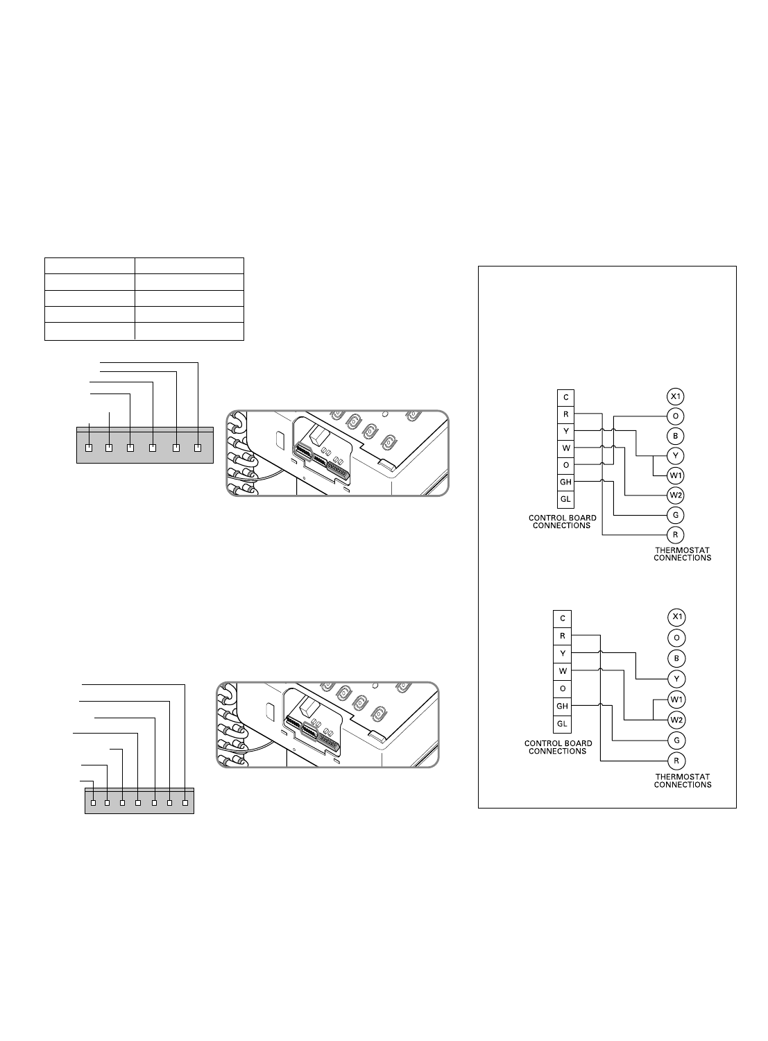
Wiring Schematic for
Remote Heat Pump
Wiring Schematic for
Straight Cool Unit.
—11—
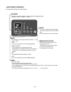
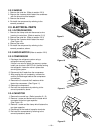
• REMOTE/LOCAL CONTROL
When remote/local switch #1 is on, it allow the unit to operate by the Remote Wall Thermostat.
The unit control by knobs are not available.
• ENERGY SAVER
The energy saver switch #2 is on. This switch is set at cycle fan to provide continuous fan operation in cool or heat modes.
When the switch is off the continuous fan allows continuous circulation of room air and make the more balanced temperature
of the room. When the switch is on, the fan is on or off with the compressor or with the heater.
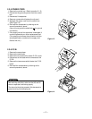
• FRONT DESK CONTROL
When the pair wire is connected to the connector FD2 and FD1, the unit can be turned ON or OFF with a switch located at the
Front Desk Control panel. When the front desk switch is ON, the fan operates according to the setting without working
compressor and heater. When the front desk switch is OFF, the unit can operate according to the setting of controls.
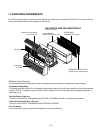
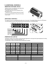
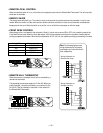
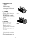
• REMOTE WALL THERMOSTAT
When the wires are connected, the unit will be controlled by a remote wall
thermostat.
The thermostat connections supply the 24 Volt AC. When you install the
digital/electronic thermostat, you must set it to 24 Volt AC. See the
installation Instruction in this manual for the Remote Wall Thermostat.
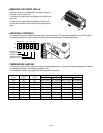
Note: The following figures show wiring
schematics for heat pump and straight
cool units with electric heat, respectively.
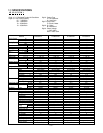
GL GH O W Y R C
Low Fan
High Fan
Reversing Valve
Heater
Compressor
24 Volt-L
24 Volt-N
Wire # AWG Maximum Length
#22
600 ft (180 m)
#20 900 ft (270 m)
#18 1500 ft (450 m)
#16 2000 ft (610 m)
FD2 FD1 DR2 DR1 MS2 MS1
Front Desk Control
Front Desk Control
Door Switch
Door Switch
Motion Sensor
Motion Sensor
(Molex Housing Spec 396-06V)
(Molex Housing Spec 396-07V)