


Page 30
FIGURE 38
COVER EXHAUST
VENT WITH
1/2" (13)
FOAM
INSULATION
Front View
Side View
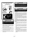
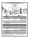
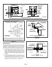
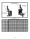
DIRECT VENT TERMINATION
WALL TERMINATION KIT (22G44, 44J40, 30G28 or 81J20) EXTENDED VENT FOR GRADE CLEARANCE
Inches (mm)
5"
(127)
5-1/2"
(140)
EXHAUST
AIR
INTAKE
AIR
GRADE
12"
(305)
8" (203)
Minimum
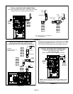
INTAKE
AIR
EXHAUST
AIR
GRADE
12" (305) MAX. for 2" (51)
20" (508) MAX. for 3" (76)
(unless supported)
Minimum 12"
(305)
above grade or
average snow
accumulation.
Minimum 12"
(305)
above grade or
average snow
accumulation.
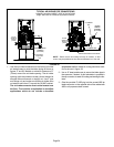
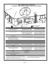
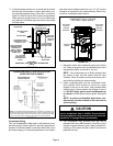
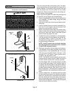
G61MP DIRECT VENT APPLICATION
USING EXISTING CHIMNEY
NOTE − Do not discharge exhaust gases directly into any chimney or vent stack. If ver-
tical discharge through an existing unused chimney or stack is required, insert piping
inside chimney until the pipe open end is above top of chimney and terminate as illus-
trated. In any exterior portion of chimney, the exhaust vent must be insulated.
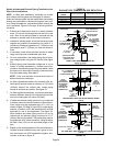
FIGURE 39
8" − 12"
(203mm − 305mm)
3" − 8"
(76mm−
203mm)
3" − 8"
(76mm−
203mm)
STRAIGHT−CUT OR
ANGLE−CUT IN DIRECTION
OF ROOF SLOPE *
EXHAUST VENT
1/2" (13mm)
WEATHERPROOF
INSULATION
SHOULDER OF FITTINGS
PROVIDE SUPPORT
OF PIPE ON TOP PLATE
ALTERNATE
INTAKE PIPE
INTAKE PIPE
INSULATION (optional)
EXTERIOR
PORTION OF
CHIMNEY
INSULATE
TO FORM
SEAL
SHEET
METAL TOP
PLATE
MINIMUM 12"
(305mm) ABOVE
ROOF
*SIZE TERMINATION
PIPE PER TABLE 8.
Minimum 12" (305)
above roof or average
snow accumulation.
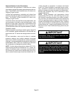
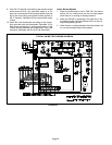
Details of Exhaust Piping Terminations for Non-Direct
Vent Applications
Exhaust pipes may be routed either horizontally through an
outside wall or vertically through the roof. In attic or closet
installations, vertical termination through the roof is pre-
ferred. Figures 40 through 43 show typical terminations.
1 − Exhaust piping must terminate straight out or up as
shown. The termination pipe must be sized as listed in
table 8.The specified pipe size ensures proper veloc-
ity required to move the exhaust gases away from the
building.
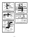
2 − On field supplied terminations for side wall exits, ex-
haust piping should extend a maximum of 12 inches
(305mm) beyond the outside wall, unless support is
provided in the horizontal section. See figure 41.
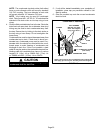
FIGURE 40
NON−DIRECT VENT ROOF TERMINATION KIT
(15F75 or 44J41)
UNCONDITIONED
ATTIC SPACE
3" (76) OR
2" (51) PVC
PROVIDE SUPPORT
FOR EXHAUST LINES
Inches(mm)
12" (305mm)
ABOVE AVE.
SNOW
ACCUMULATION
SIZE TERMINATION
PIPE PER TABLE 8.
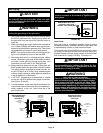
FIGURE 41
1/2" (13) ARMAFLEX
INSULATION IN
UNCONDITIONED SPACE
12" (305) Max. for 2" (51)
Unless Supported
PVC REDUCER
1/2" (13)
ARMAFLEX
INSULATION
Inches (mm)
TOP VIEW
NON−DIRECT VENT WALL RING KIT
(15F74)
SIZE TERMINATION
PIPE PER TABLE 8.
FIELD−PROVIDED
REDUCER MAY
BE REQUIRED TO
ADAPT LARGER
VENT PIPE SIZE
TO TERMINATION