


Page 10
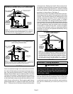
Upflow Applications
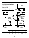
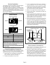
The G61MP gas furnace can be installed as shipped in
the upflow position. Refer to figure 8 for clearances.
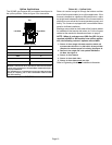
Installation Clearances
Top
Bottom (Floor)
Left Side
Right Side
Top/Plenum 1 in. (25 mm)
*Front 0
Back 0
Sides 0†
Vent 0
Floor 0‡
*Front clearance in alcove installation must be 24 in. (610 mm).
Maintain a minimum of 24 in. (610 mm) for front service access.
†Allow proper clearances to accommodate condensate trap and
vent pipe installation.
‡For installations on a combustible floor, do not install the furnace
directly on carpeting, tile or other combustible materials other
than wood flooring.
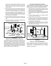
FIGURE 8
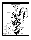
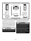
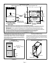
Return Air −− Upflow Units
Return air can be brought in through the bottom or either
side of the furnace installed in an upflow application. If the
furnace is installed on a platform with bottom return, make
an airtight seal between the bottom of the furnace and the
platform to ensure that the furnace operates properly and
safely. The furnace is equipped with a removable bottom
panel to facilitate installation.
Markings are provided on both sides of the furnace cabinet
for installations that require side return air. Cut the furnace
cabinet at the maximum dimensions shown on page 2.
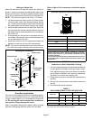
NOTE − When air volumes over 1800 cfm (850 L/s) are
required with 60C or 60D models in an upflow applica-
tion, the following return air options are available:
1 − Return air from single side with transition which will
accommodate 20 x 25 x 1 in. (508 x 635 x 25 mm) air filter.
(Required to maintain proper air velocity.) See figure 10.
2 − Return air from single side with optional RAB Return
Air Base. See figure 9.
3 − Return air from bottom.
4 − Return air from both sides.
5 − Return air from bottom and
one side.
Refer to Engineering Handbook for additional information.