


Page 15
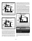
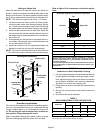
Lennox part number 56J18). Position the support
frame on top of the blocks and install the unit on the
frame. Leave 5−1/2 inches for service clearance for
condensate trap.
3 − Route auxiliary drain line so that water draining from
this outlet will be easily noticed by the homeowner. If
necessary, run the condensate line into a condensate
pump to meet drain line slope requirements. The
pump must be rated for use with condensing furnaces.
Protect the condensate discharge line from the pump
to the outside to avoid freezing.
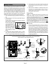
4 − Set unit in drain pan as shown in figure 19. Leave 5−1/2
inches for service clearance below unit for condensate
trap.
5 − Continue with exhaust, condensate and intake piping
installation according to instructions.
INTAKE PIPE
*GAS
CONNECTOR
SERVICE PLATFORM
RAISED
PLATFORM
CONDENSATE LINE
*Gas connector may be
used for Canadian
installation if accept-
able by local authority
having jurisdiction.
EXHAUST PIPE
FIGURE 19
G61MP Installed in Unit Heater Applications
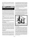
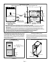
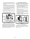
The G61MP may also be installed as a unit heater. Either
suspend the furnace from roof rafters or floor joists, as
shown in figure 18, or install the furnace on a field−fabri-
cated raised platform, as shown in figure 19. The unit must
be supported at both ends and beneath the blower deck to
prevent sagging. The condensate trap must be installed
where it can be serviced at a later date.
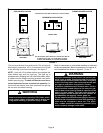
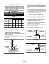
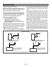
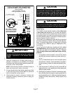
Unit Heater Discharge Duct Guidelines
A field−fabricated and installed discharge air duct and grille
cabinet is suitable for use with the G61MP heater. Keep the
following items in mind when constructing the cabinet.
1 − Outer dimensions of cabinet should match those of the
unit heater, so the duct/grille cabinet installs flush with
the unit heater cabinet. See figure 20.
2 − Flange both ends of duct/grille cabinet so that screws
can be used to secure cabinet to discharge end of unit
heater.
3 − To ensure proper operation, the duct/grille cabinet
must be at least 18 inches long.
4 − Use #10−16 x 1/2 inch sheet metal screws to secure
duct/grille cabinet to unit, taking care not to damage in-
ternal components of unit heater when drilling holes or
installing screws. See figure 20.
5 − Use adjustable, double−deflection grille(s) to distribute
discharge air. Adjust static pressure to be in the 0.06
inch to 0.10 inch w.c. range.
FIGURE 20
18 in.
MIN.
NOTE − When installing duct/grille cabinet, take care not to damage internal unit
heater components when drilling holes or installing screws.
DRAIN PAN
(to protect
finished
space)
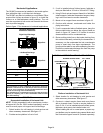
Return Air −− Horizontal Applications
Return air may be brought in only through the end of a fur-
nace installed in the horizontal position. The furnace is
equipped with a removable bottom panel to facilitate
installation. See figure 11.