


Page 18
Vent Piping Guidelines
The G61MP can be installed as either a Non−Direct Vent
or a Direct Vent gas central furnace.
NOTE − In Non-Direct Vent installations, combustion air is
taken from indoors and flue gases are discharged outdoors.
In Direct Vent installations, combustion air is taken from out-
doors and flue gases are discharged outdoors.
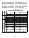
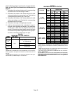
Intake and exhaust pipe sizing in Direct Vent applications
and exhaust pipe sizing in Non-Direct Vent applications −−
Size pipe according to tables 6 and 7. Table 6 lists the mini-
mum equivalent vent pipe lengths permitted. Table 7 lists
the maximum equivalent pipe lengths permitted.
Maximum vent length is defined as:
Total length (linear feet) of pipe,
Plus Equivalent length (feet) of fittings,
Plus Equivalent length (feet) of termination.
NOTE − Include ALL pipe and ALL fittings, both in
doors and outdoors.
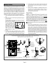
Regardless of the diameter of pipe used, the standard roof
and wall terminations described in section Exhaust Piping
Terminations should be used. Exhaust vent termination
pipe is sized to optimize the velocity of the exhaust gas as
it exits the termination. Refer to table 8.
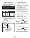
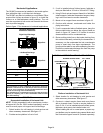
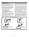
*NOTE − The exhaust pipe should be offset a minimum of
12 inches to avoid the possibility of water droplets being re-
leased from the exhaust termination. The minimum ex-
haust vent length is 15 ft. Shorter exhaust vent lengths may
result in the discharge of water droplets from the exhaust
termination, in spite of the 12−inch vertical offset. See fig-
ure 21.
Each 90° elbow (including those provided with the furnace)
of any diameter is equivalent to 5 feet (1.52m) of vent pipe
of the same diameter. Two 45° elbows are equivalent to
one 90° elbow of the same diameter. One 45° elbow is
equal to 2.5 feet (.76m) of vent pipe of the same diameter.
In some applications which permit the use of several differ-
ent sizes of vent pipe, a combination vent pipe may be
used. Contact the Application Department for assistance in
sizing vent pipe in these applications.
NOTE − The flue collar on all models is sized to accommo-
date 2" Schedule 40 flue pipe. When vent pipe which is
larger than 2" must be used in an upflow application, a 2"
elbow must be applied at the flue collar in order to proper-
ly transition to the larger diameter flue pipe. This elbow
must be added to the elbow count used to determine ac-
ceptable vent lengths. Assign an equivalent feet value to
this elbow according to the larger size pipe being used.
Contact Lennox’ Application Department for more infor-
mation concerning sizing of vent systems which include
multiple pipe sizes.
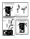
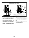
FIGURE 21
Exhaust Pipe Offset
*12" Min.
*12" Min.
*12" Min.
12" Min.
Upflow and Downflow Application
Rooftop Termination
Upflow and Downflow Application
Side Wall Termination
Horizontal Application
Rooftop Termination
Horizontal Application
Side Wall Termination
*A minimum of 1/4" (6mm) drop for each 12" (305mm) of horizontal run is mandatory for drainage