


2 - Have a shallow pan ready to empty condensate wa-
ter. Avoid spilling water into the control box.
3 - Remove clamp from flue assembly and remove boot
or cap. Empty water from cap. Visually inspect bot-
tom of flue assembly. Replace boot and clamp.
4 - Remove boot from condensate trap and empty wa-
ter. Inspect trap then replace boot.
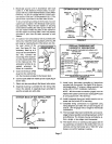
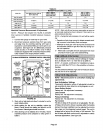
Cleaning DuralokPlus TM Heat Exchanger
If cleaning the heat exchanger is necessary, follow the
procedures below, and refer to figure 1 while you disas-
semble the furnace. Place papers or protective covering
in front of the furnace while you remove the heat exchang-
er assembly.
1 - Turn off electrical and gas power supplies to fumaea.
2 - Remove upper and lower furnace access panels.
3 - Remove four screws around air intake fitting and lift
intake pipe up and away.
4 - Loosen hose clamp securing top of flue transition to
bottom of flue collar. Remove screw secudng flue
collar to top cap and lift exhaust pipe and flue collar
up and away.
5 - If electrical field make-up box is located inside the
unit, it must be removed.
6 - Remove gas supply line connected to gas valve.
7 - Mark all gas valve wires and disconnect them from
valve. Mark and remove wires from flame roll-out
switch.
8 - Remove top cap of unit.
9 - Remove sensor wire from SureLight_ control. Dis-
connect 2-pin plug from the ignitor.
10 - Mark and disconnect pressure switch tubing from
both sides of the pressure switch(es).
11 - Loosen two screws holding gas manifold support at
vestibule panel.
12 - Remove four burner box screws at the vestibule pan-
ei and remove burner box and gas valve/manifold as-
sembly with bracket.
13 - Drain condensate trap. Disconnect condensate line
from the outside of unit. Remove condensate line
from condensate trap by turning the adapter fitting
counterclockwise. The fitting has standard right
hand threads.
14 - Disconnect the drain hose from the flue transition to
the elbow on the cold header (collector) box trap.
15 - Disconnect the 3-pin plug from the combustion air in-
ducer at the blower deck. Remove four screwsfrom
combustion air inducer and remove flue transition
and inducerassemblyfrom cabinet.Take care notto
lose the combustionair orifice.
16 - Mark and disconnectall remaining wires from heat-
ing compartment components.
17 - Disengage strain relief bushing from blower deck
and pull bushing and wires into the blower section.
18 - Remove the limit switch and the pressure switch(es)
from the vestibule panel.
19 - Remove two screws from the front cabinet flange at
the blower deck. Remove front screws from cabinet
at blower deck on left and right sides. Cabinet sides
must be slightly spread to clear heat exchanger pas-
sage.
20 - Remove screws along vestibule sides and bottom
which secure vestibule panel and heat exchanger
assembly to cabinet. Remove heat exchanger.
21 - Back wash heat exchanger with soapy water solu-
tion or steam. If steam is used it must be below
275°F (135°C).
22-Thoroughly rinse and drain the heat exchanger.
Soap solution can be corrosive so take care that en-
tire assembly is completely dnsed.
23 - Reinstall heat exchanger into cabinet making sure
that the clamshells of the heat exchanger assembly
are resting in the notches of the support located at
the rear of the cabinet. This can be viewed by remov-
ing the indoor blower and examining through the
blower opening.
24 - Resecure the supporting screws along the vestibule
sides and bottom to the cabinet.
25 - Reinstall cabinet screws on sides and front flange at
blower deck.
26 - Reinstall the limit switch and pressure switches on
the vestibule panel.
27 - Route heating component wiring back through the
hole in the blower deck and reinsert strain relief
bushing.Reconnectwires.
28 - Reinstall the combustion air inducer. Check to en-
sure that the plastic orifice on the blower inlet has not
fallen out. See figure 1. Reconnect the 3-pin plug to
the wire harness. Reinstall the flue transition in the
cabinet and reattech the drain tube. Routethe drain
tube below the combustion air inducer housing and
to the elbow on the cold header (collector) box trap.
See figure 35.
29 - Reinstall condensate line with adapter to condensate
trap. Use fresh Teflon tape to ensure a leak-freejoint.
Re-connectto condensate line outside of the unit.
30 - Reinstall the burner box. Tighten the screws holding
the support bracket. It is important that the glass fiber
gasket not be damaged so it will provide a continu-
ous seal between the burner box and the vestibule
panel.
31 - Reconnect pressure switch tubing by connecting the
tubing from the bomer box to the barbed fitting on the
bottom and the tubing from the combustion air induc-
er to the barbed fittingon the top. See figure 35.
32 - Reconnect the sensor and ignitor wires.
33 - Reinstall top cap to unit.
Page25