


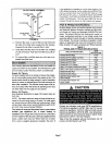
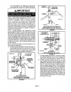
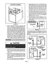
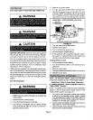
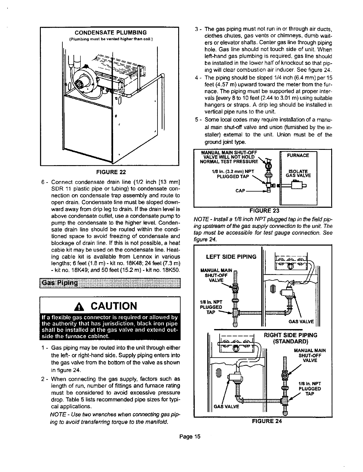
CONDENSATE PLUMBING
(Plumbing must be vented higher than coll.)
FIGURE 22
6- Connect condensate drain line (1/2 inch [13 mm]
SDR 11 plastic pipe or tubing) to condensate con-
nection on condensate trap assembly and route to
open drain. Condensate line must be sloped down-
ward away from drip leg to drain. If the drain level is
above condensate outlet, use a condensate pump to
pump the condensate to the higher level. Conden-
sate drain line should be routed within the condi-
tioned space to avoid freezing of condensate and
blockage of drain line. If this is not possible,a heat
cable kit may be used on the condensate line. Heat-
ing cable kit is available from Lennox in various
lengths; 6 feet (1.8 m) - kit no. 18K48; 24 feet (7.3 m)
- kit no. 18K49; and 50 feet (15.2 m) - kit no. 18K50.
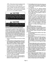
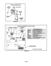
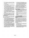
1 - Gas piping may be muted into the unitthrough either
the left- or right-hand side. Supply piping enters into
the gas valve from the bottom of the valve asshown
in figure 24.
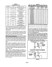
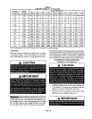
2- When connecting the gas supply, factors such as
length of run, number of fittings and furnace rating
must be considered to avoid excessive pressure
drop. Table 5 lists recommended pipe sizes for typi-
cal applications.
NOTE - Use two wrenches when connecting gas pip-
ing to avoid transferring torque to the manifold.
3 - The gas piping must not run in or through air ducts,
clothes chutes, gas vents or chimneys, dumb wait-
ers or elevator shafts. Center gas line through piping
hole. Gas line should not touch side of unit. When
left-hand gas plumbing is required, gas line should
be installed in the lower half of knockout so that pip-
ing will clear combustion air inducer. See figure 24.
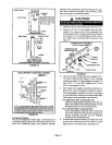
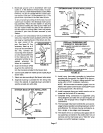
4 - The piping should be sloped 1/4inch (6.4 mm) per 15
feet (4.57 m) upward toward the meter from the fur-
nace. The piping must be supported at properinter-
vals [every 8to 10 feet (2.44 to 3.01m) using suitable
hangers or straps. A drip leg should be installed in
vertical pipe runs to the unit.
5 - Some local codesmay require installationof a manu-
al main shut-off valve and union (furnished by the in-
staller) external to the unit. Union must be of the
groundjointtype,
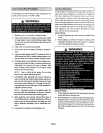
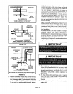
II
CAP-_D-I_I U
FIGURE 23
NOTE - Install a 1/8 inch NPTplugged tap in the field pip
ing upstream ofthe gas supplyconnection to the unit.The
tap must be accessible for test gauge connection. See
figure 24.
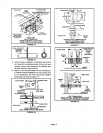
LEFT SIDE PIPING
MANUAL MAIN
SHUT-OFF
VALVE
1/8in. NPT
PLUGGED
TAP
GAS VALVE
.... --I, RIGHT SIDE PIPING
_(.=.___=.-,_t_ (STANDARD)
118In. NPT
PLUGGED
..........................j,AP
GAS VALVE
FIGURE 24
Page 15