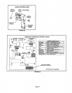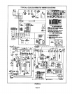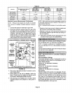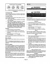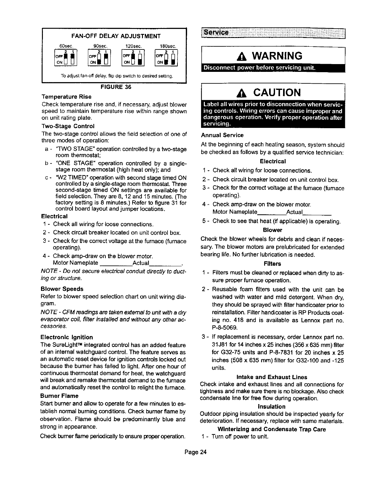
FAN*OFFDELAYADJUSTMENT
60sec, 90sec. 120sec, 180sec.
To adjust fan-off delay, flip dip switch to desired setting.
FIGURE 36
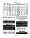
Temperature Rise
Check temperature rise and, if necessary, adjust blower
speed to maintain temperature rise withinrange shown
on unit rating plate.
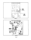
Two-Stage Control
The two-stagecontrolallows the field selection of one of
three modes of operation:
a - "TWO STAGE"operationcontrolledby a two-stage
room thermostat;
b- "ONE STAGE" operation controlled by a single-
stage room thermostat(high heat only); and
c - "W2 TIMED" operationwithsecondstage timedON
controlledby a single-stageroomthermostat.Three
second-stage timed ON settings are available for
field selection. They are 8, 12 and 15 minutes.(The
factory setting is 8 minutes.) Refer to figure 31 for
controlboard layout and jumper locations.
Electrical
1 - Check all wiringfor loose connections.
2 - Check circuitbreaker located on unit controlbox.
3 - Check for the correct voltage at thefurnace (furnace
operating).
4 - Check amp-draw on the blower motor.
Motor Nameplate Actual
NOTE - Do not secure electrical conduit directly to duct-
ing or structure.
Blower Speeds
Refer to blower speed selection chart on unit wiring dia-
gram.
NOTE - CFM readings are takenextema/to unitwitha dry
evaporator coil fi/ter insta//ed and without any other ac-
cessories,
Electronic Ignition
The SureLight TM integratedcontrol hasan added feature
of an internal watchguardcontrol The feature serves as
an automatic reset devicefor ignitioncontrotslockedout
because the burner has failed to light.After one hourof
continuousthermostat demand for heat, the watchguard
will break and remake thermostatdemand to the furnace
and automaticallyreset the controlto relightthe furnace.
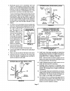
Bumer Flame
Start burnerand allow to operate for a few minutestoes-
tablishnormalburningconditions.Check burner flame by
observation. Flame should be predominantly blue and
strongin appearance.
Check burnerflame periodicallytoensure properoperation.
CAUTION
Annual Service
At the beginning of each heating season, systemshould
be checked as follows by a qualified service technician:
Electrical
1 - Check all wiringfor loose connections.
2 - Check circuitbreaker located on unitcontrolbox,
3 - Check forthe correctvoltageat the furnace(furnace
operating).
4 - Check amp-draw on the blower motor.
Motor Nameplate Actual
5 - Check to see that heat (if applicable) is operating.
Blower
Check the blowerwheels for debris and clean if neces-
sary. The blower motors are prelubricated for extended
bearing life. No further lubdcetion is needed.
Filters
1 - Filtersmustbe cleanedor replaced whendirtytoas-
sure proper furnaceoperation.
2- Reusable foam filters used with the unit can be
washed with water and mild detergent. When dry,
they shouldbe sprayedwithfilterhandicoaterpdorto
reinstallation.FilterhandicoaterisRP Productscoat-
ing no. 418 and is available as Lennox part no.
P-8-5069.
3 - If replacement is necessary, order Lennox part no.
31J81 for 14 inchesx 25 inches(356 x 635 ram) filter
for G32-75 units and P-8-7831 for 20 inches x 25
inches (508 x 635 ram) filterfor G32-100 and -125
units.
Intake and Exhaust Lines
Check intake and exhaust lines and all connections for
tightnessand make surethere is noblockage,hJsocheck
condensate linefor free flowdudng operation.
Insulation
Outdoor pipinginsulationshoutdbe inspectedyeady for
deterioration. If necessary,replace withsame materials.
Winterizing and Condensate Trap Care
1 - Turn off powerto unit.
Page 24


