


506052−01 11/09
Page 36
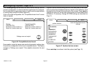
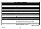
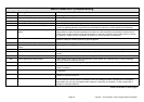
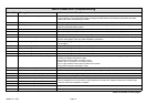
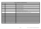
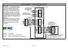
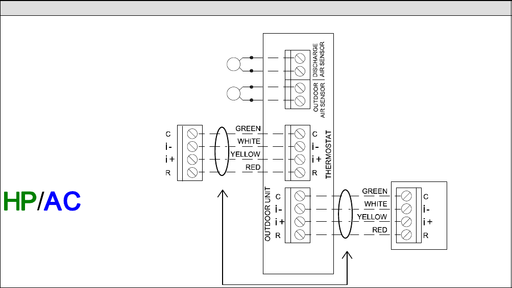
Wiring Diagrams − Communicating Systems
icomfortt
FURNACE (IFC) OR AIR HANDLER (AHC)
icomfortt
THERMOSTAT
icomfortt
OUTDOOR AIR
CONDITIONING OR
HEAT PUMP UNIT
OPTIONAL OUT-
DOOR AIR SENSOR
(SEE OAS NOTE)
OPTIONAL DIS-
CHARGE AIR SEN-
SOR (SEE DAS
NOTE)
icomfortt Thermostat
icomfortt Indoor Furnace or Air Handler
icomfortt Outdoor Condensing Unit or Heat Pump
DAS NOTE − The discharge air sensor
is intended to be mounted downstream
of the heat exchanger and air condi-
tioning coil. It must be placed in free
airflow, where other accessories (such
as humidifiers, UV lights, etc.) will not
interfere with its accuracy. Wiring dis-
tance between the IFC or AHC and the
discharge air sensor should not exceed
10ft when wired with 18−gauge thermo-
stat wire.
OAS NOTE − Wiring distance between
the IFC or AHC and the outdoor tem-
perature sensor should not exceed
200ft when wired with 18−gauge ther-
mostat wire.
Maximum total length of all connections
on the RSBus is limited to 1500ft.
Wire gauge of RSBus wire is 18.
RSBus
RSBus