


Facade Installation
Install the Facade per instructions provided in
Facade Kit (ordered separately - see Page 20).
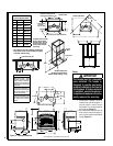
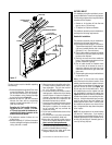
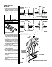
Framing, Facing And Mantel
The construction of the framing, facing, and
mantel must be in accordance with the stan-
dards and the following illustrations (Figures
10 and 11):
A.Framethereplaceusing2”x3”orheavier
lumber.
B. WARNING: Combustible materials can-
not be used in the space directly above
the fireplace, except for the studs above
the facade that support the facing and
mantel. This area must remain empty
for a height of 6’8” (2,032 mm) mea-
sured from the base of the appliance.
C. Frame the fireplace with vertical studs at the
sides of the fireplace running from floor to
ceiling (see Figure 8). If combustible facing
is to be used, position the studs back, from
the front edge of the fireplace (a space that
is the thickness of the facing material, so
that the facing can be installed flush with the
fireplace facing). Frame headers between
the vertical studs only as follows:
• Place2” x3” or 2”x 4”headers,
only along the upper part of the front,
side and back faces (some codes
mayrequirea2”x6”onanoutside
bearing wall). Do not put wood or
any combustible material within the
area above the fireplace except on the
front facing.
• Placeheadersonlyasrequiredtosup-
port the facing and mantel.
D. WARNING: The fireplace must not be in
contact with any insulation or loose fill-
ing material. Cover the insulation with
drywall panels around the fireplace.
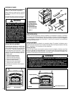
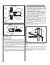
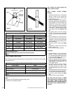
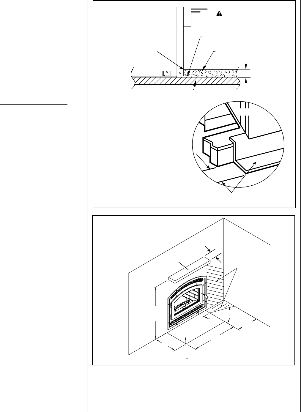
Hearth Extension Requirements
The Brentwood fireplace may be installed
directly on a combustible floor. The supplied
safety metal strip must be positioned as fol-
lows: One half under the front of the fireplace
and the other half must extend on the floor
over which the hearth extension will be built
(see Figure 7A).
* The safety metal strip must cover the entire
width of the fireplace.
The combustible floor in front of the fireplace
must be covered with a non-combustible mate-
rial (tile, marble, stone, etc). See Figures 7B.
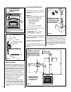
COLD CLIMATE INSTALLATIONS
Climates where temperatures will fall below
32° F (0° C).
The heating performance of the appliance will
vary depending upon the level of insulation,
house design, how the appliance is operated,
etc.
If this fireplace is being installed in a cold
climate, it is especially important to seal all
cracks around the fireplace and wherever cold
air could enter the room with noncombustible
material.
Also,theoutsideairinletductshouldbewrappedwithnoncombustibleinsulationtominimize
the formation of condensation. Do not place insulation materials directly against the chimney
sections. We recommend that you use the insulated wall radiation shield since it will maintain the
home’s thermal barrier. AC chimney is NOT recommended in very cold climates (in areas with
temperatures below 0°F (-18°C).
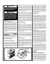
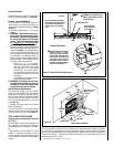
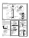
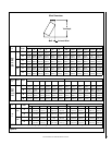
Figure 7B
42”
(1067mm)
Min.
18”
Area where wood
Mantel can be
installed
Non-Combustible Material
45 Deg.
4”
36”
17” Min.
Hearth
Extension
(457mm)
(914mm)
(432mm)
(102mm)
Mantel
WARNING: THE HEARTH EXTEN-
SION IS TO BE INSTALLED ONLY
AS ILLUSTRATED.
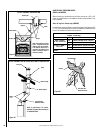
The crack between the fireplace
and the hearth extension must be
sealed with a non-combustible
material such as sand-cement
grout.
Safety Metal Strip
Hearth Extension
Non-Combustible
Finish Material
Floor
Figure 7A - Hearth Extension Requirements
Fireplace
1/2”
13mm
u Elevated fireplace installations
require a special “Z” Metal
Safety Strips (field provided),
in place of the safety metal strip
shown above. The safety strip
should extend the full width of
the fireplace. When more than
one safety strip is used they must
overlap by a minimum of 1”.
Platform
2”
Fireplace
Elevated Fireplaces
u
12”
MAX
7
NOTE:DIAGRAMSandILLUSTRATIONSARENOTTOSCALE.