


24
NOTE: DIAGRAMS & ILLUSTRATIONS ARE NOT TO SCALE.
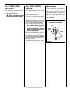
Test All Connections for Gas Leaks
(Factory and Field)
WARNING
Never use an open flame to
check for leaks.
Turn on gas supply and test for gas leaks using a
gas leak test solution (also referred to as bubble
leak solution).
Note: Using a soapy water solution is an effec-
tive leak test solution but it is not recommended,
because the soap residue that is left on the pipes/
fittings can result in corrosion over time.
A. Light the appliance. See the lighting instruc-
tions label in the replace control compart-
ment or Care and Operation Instructions.
B. Brush all joints and connections with the gas
leak test solution to check for leaks. If bubbles
are formed, or gas odor is detected, turn the
receiver or remote control to the OFF position.
Either tighten or refasten the leaking connection;
then retest as described above.
C. When the gas lines are tested and leak-free,
be sure to rinse off the leak testing solution.
D. Reinstall the access plate, making certain the
gasket has not been damaged.
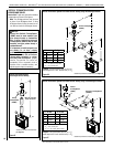
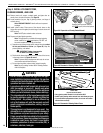
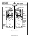
Step 6. CONNECT GAS LINE
All codes require a shut-off valve mounted in the
supply line. The orientation of the shut-off valve
should face the front. Figure 36 illustrates two
methods for connecting the gas supply. A Sedi-
ment Trap is recommended to prevent moisture
and debris in gas line from damaging the valve.
The ex-line method is acceptable in the U.S.A
where local codes permit; however, Canadian
requirements vary depending on local codes.
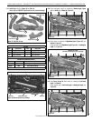
See Figure 36 for flex-line description. The
ex-line is rated for both natural and propane
gas. A manual shut off valve is also provided
with the flex-line.
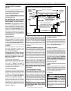
The gas control valve is located on the right
side of the unit.
When using solid gas line connector, access the
valve by removing the glass door assembly on
the control side (see Page 29) and the access
plate (see Figure 37).
The electronic control valve has a 3/8" (10 mm)
NPT thread gas supply inlet.
Bring the shutoff valve on the end of the ex-line
over to the hard pipe and tighten with wrenches
from above through the rebox opening.
Secure all joints tightly using appropriate tools
and sealing compounds (ensure propane-
resistant compounds are used in propane
applications). Seal around gas line to prevent
cold air leakage. Use sealants approved by
local codes for the application.
Gas
Valve
3/8" NPT x
Flare Fitting
3/8" Flex Tubing
3/8" Nipple
3/8" Union
3/8" Close
Nipple
3/8" Shut-off Valve
1/2" x 3/8"
Reducer
Gas
Stub
1/2" x 3/8" Flare
Shut-off Valve
Gas Solid Line Connector
Gas Flex Line Connector
*Sediment
Trap
3"
Min
Note: The gas supply line
must be installed in accor-
dance with building codes
by a qualified installer
approved and/or licensed
as required by the locality.
In the Commonwealth of
Massachusetts, installation
must be performed by a
licensed plumber or gas
fitter.
Figure 36
GAS CONNECTION
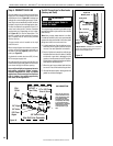
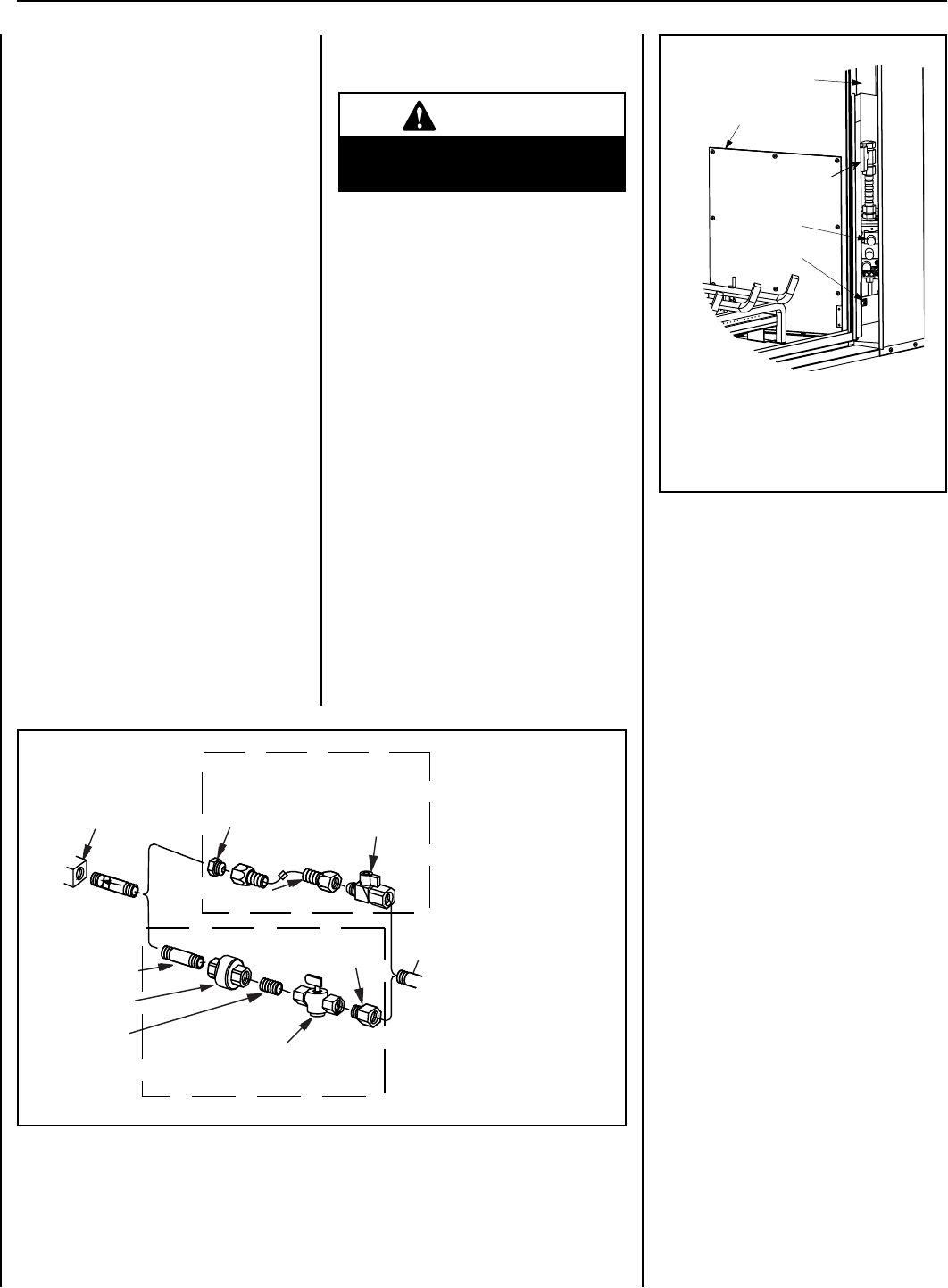
*ON/OFF Switch - Switches from intermittent
ignition to a standing pilot (a standing pilot
stays lit when replace is off).
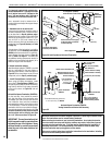
Right Side
Modesty Panel
Access Panel
ON/OFF Switch*
Gas Valve
Control
Compartment
Access
Figure 37
Main Gas
Shut-Off Valve
LENNOX HEARTH PRODUCTS • MONTEBELLO
®
SEE-THROUGH DIRECT-VENT GAS FIREPLACES (LSM40ST-N / LSM40ST-P) • INSTALLATION INSTRUCTIONS