


NOTE: DIAGRAMS & ILLUSTRATIONS ARE NOT TO SCALE.
17
LENNOX HEARTH PRODUCTS • MONTEBELLO
®
SEE-THROUGH DIRECT-VENT GAS FIREPLACES (LSM40ST-N / LSM40ST-P) • INSTALLATION INSTRUCTIONS
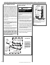
G. Continue installation of horizontal/
inclined sections.
Continue with installation of the straight vent
sections in horizontal/inclined run as de-
scribed in Step C. Install support straps every
3 ft (914 mm) along horizontal/inclined vent
runs using conventional plumber’s tape (see
Page 19, Figure 28).
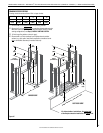
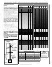
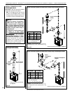
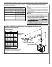
Figure 21
Framing Dimensions for Roof
Pitch C D
0/12
13 in
(330 mm)
13 in
(330 mm)
6/12
13 in
(330 mm)
15-1/2 in
(394 mm)
12/12
13 in
(330 mm)
20-1/2 in
(541 mm)
C
D
Figure 22: Roof Framing
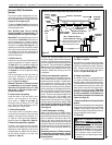
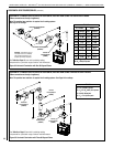
Figure 23
Storm
Collar
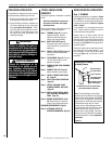
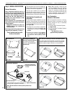
I. Install roof flashing.
Extend the vent sections through the roof
structure. Install the roof flashing over the
vent section and position such that the vent
column rises vertically (use carpenters level)
(Figure 23 ). Nail along perimeter to secure
ashing or adjust roong to overlap the ash-
ing edges at top and sides only and trim where
necessary. Seal the top and both sides of the
flashing with waterproof caulking.
J. Install storm collar.
Install the storm collar, supplied with the
ashing, over the vent/ashing joint (see
Figure 23). Loosen the storm collar screw.
Slide collar down until it meets the top of the
ashing. Tighten the adjusting screw. Apply
non-combustible caulking or mastic around
the circumference of the joint to provide a
water tight seal.
Storm
Collar
Flashing
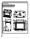
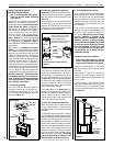
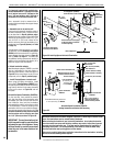
Figure 24
If the vent system extends more than 5 ft (1.5
m) above the roof ashing, stabilizers may be
necessary.
Additional screws may be used at section joints
for added stability.
Guide wires may be attached to the joint for ad-
ditional support on multiple joint congurations.
K. Install vertical termination.
The final step involves installation of the verti-
cal termination. Extend the vent sections to the
height as shown in “Vertical Vent Termination
Clearances” on Page 6.
The vertical termination (Figure 24) installs
in the same manner as other Secure Vent™
sections. Align the termination over the end of
the previously installed section, adjusting the
radial alignment until the four locking dimples
of the termination are aligned with the inlets of
the four incline channels of the last vent section.
Push the termination down until it fully engages,
then twist the termination clockwise, running
the dimples down and along the incline chan-
nels until they seat at the end of the channels.
6"
(153 mm)
10"
(254 mm)
Note: It is important to maintain the required
clearances to combustibles: 1" (25 mm) at
all sides for all vertical runs; and 4" (102
mm) at the top, 1" (25 mm) at sides, and
1" (25 mm) at the bottom for all horizontal/
inclined runs.
H. Frame roof opening.
Identify location for vent at the roof. Cut and/
or frame opening per Roof Framing Chart (see
Figure 22).
NOTICE: It is important to install
horizontal runs on a steady, (i.e., no
“dips”), slightly positive incline of
approximately 1/4 inch rise-per-foot (20
millimeters rise-per-meter) horizontal,
in a direction away from the fireplace.
(Slightly smaller rise-per-foot run ratios
are acceptable.) Use a carpenter’s level
to measure from a constant surface, and
adjust support straps as necessary.
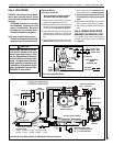
Vertical Termination System
with Offset Vertical Venting (continued)
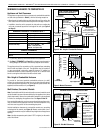
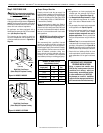
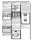
F. Change vent direction to horizontal/
inclined run.
At any transition to or from a horizontal/
inclined run, install the elbows (SV8E45,
SV8E90; see Figure 21) in the same manner
as the straight vent sections.
The elbows feature a twist section to allow
them to be routed about the center axis of their
initial collar section, to align with the required
direction of the next vent run element. Twist
elbow sections in a clockwise direction only,
to avoid the possibility of unlocking any pre-
viously connected vent section (see Figures
19 and 21).
360° Swivel Joint
(SV8E45)
45° Elbow
360° Swivel Joint
(SV8E90)
90° Elbow