


21
HORIZONTAL TERMINATION SYSTEM FIGURES/TABLES
Note:
• Secure Vent™ rigid vent pipe and termination components are shown
in the figures.
• Two 45-degree elbows may be used in place of one 90-degree elbow.
If using 45-degree elbows, follow the same rise-to-run ratios as shown
for 90-degree elbows.
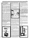
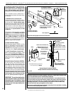
NOTICE:
Secure Vent™ Vertical Firestop/Spacer (SV8BF) must be used
anywhere vent pipe passes through a combustible floor or ceiling.
Secure Vent Horizontal Firestop/Spacer (SV8HF4) must be used
anywhere vent pipe passes through a combustible wall.
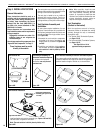
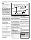
It is important to install horizontal runs on a steady, (i.e., no
“dips”), slightly positive incline of approximately 1/4 inch rise-
per-foot (20 millimeters rise-per-meter) horizontal, in a direction
away from the fireplace. (Slightly smaller rise-per-foot run ratios
are acceptable.) Use a carpenter’s level to measure from a constant
surface, and adjust support straps as necessary.
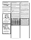
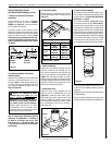
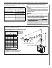
Required Venting Components (based on Exterior Wall Thickness)
when using Horizontal Square Termination Kit (SV8HTS4)
Exterior Wall Thickness Required Components
5 to 8-1/2 in (127 to 216 mm) • Termination Kit
(SV8HTS4)
9-3/4 to 14 in (248 to 356 mm) • Termination Kit (SV8HTS4)
• 6-in Vent Section (SV8L6)
6-3/4 to 15-1/4 in (171 to 387 mm) • Termination Kit
(SV8HTS4)
• Telescopic Section (SV8LA)
11-1/4 to 19-3/4 in (286 to 502 mm) • Termination Kit (SV8HTS4)
• Telescopic Section (SV8LA)
• 6-in. Vent Section (SV8L6)
Table 8
See Table 8 as an aid in venting component selection for a particular
range of exterior wall thicknesses.
LENNOX HEARTH PRODUCTS • MONTEBELLO
®
SEE-THROUGH DIRECT-VENT GAS FIREPLACES (LSM40ST-N / LSM40ST-P) • INSTALLATION INSTRUCTIONS
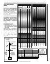
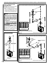
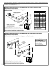
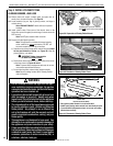
HORIZONTAL TERMINATION SYSTEM WITH HORIZONTAL/INCLINED RUN USING ONE 90-DEGREE ELBOW
(elbow connection not directly at appliance)
Note: The provided vent restrictor is required in all venting systems.
See Page 14 for settings.
V
H
Horizontal Firestop/Spacer (SV8HF4)
Vertical Firestop/Spacer (SV8BF)
Square
Termination
(SV8HTS4)
shown
Table C
H Maximum
V Minimum
feet (meters) feet (meters)
3.5 (1.07) 2.5 (0.762)
6.5 (1.98) 3.5 (1.07)
8.5 (2.6) 4.5 (1.37)
10.5 (3.2) 5.5 (1.68)
12.5 (3.8) 6.5 (1.98)
14.5 (4.4) 7.5 (2.3)
16.5 (5.0) 8.5 (2.6)
18.5 (5.6) 9.5 (2.9)
20 (6.0) 10 (3.0)
V + H = 40 ft (12.4 m) max.
H = 20 ft (6.2 m) max.
Example: 20 feet
of horizontal vent
run (H) requires a
minimum 10 feet of
vertical vent (V).
Figure 31
See Table 8 as an aid in selecting venting components
for a particular range of exterior wall thicknesses.