NOTE: DIAGRAMS & ILLUSTRATIONS NOT TO SCALE.
3
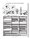
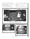
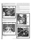
PREPARE THE FIREPLACE FOR POWER-VENTING
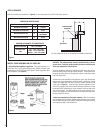
Modify fireplace for acceptance of the power vent kit. Refer to Table 1
and install the appropriate adapter kit. Follow the instructions provided
with the kit to successfully prepare the fireplace for use with power
venting. If no kit is listed, the fireplace will not require modification.
Refer to the fireplace installation instructions for details and information
detailing its compatibility with power venting. If its is not compatible, do
not power-vent the fireplace.
VENTING THE FIREPLACE
Venting Configurations
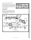
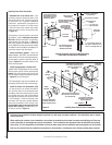
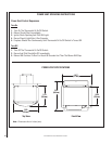
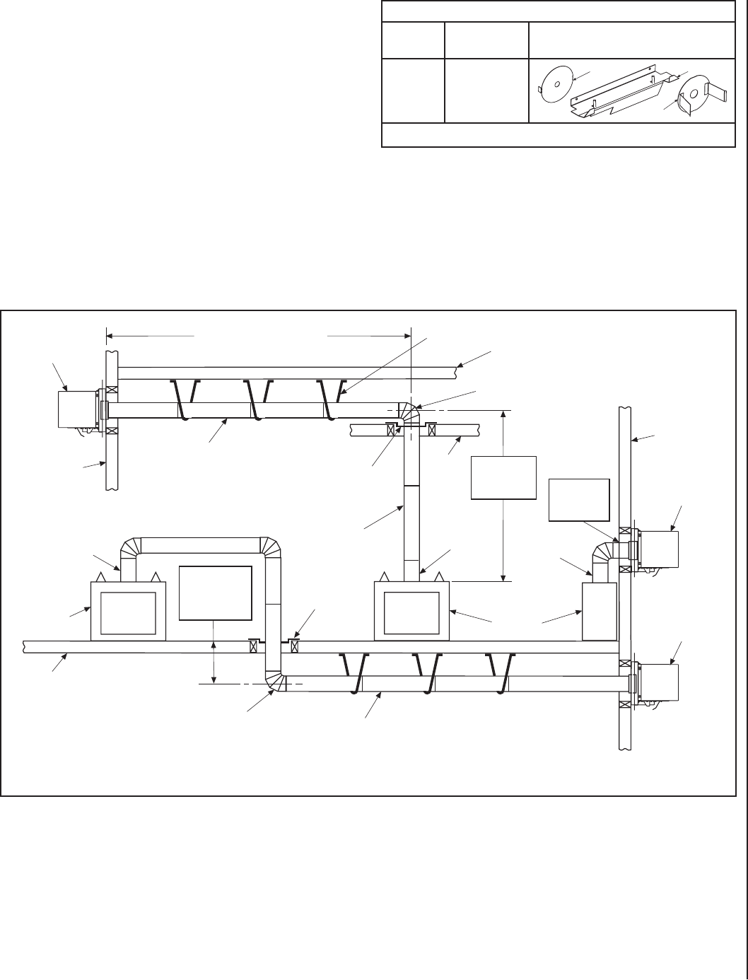
Maximum vent is 110 feet, plus six 90-degree elbows or twelve 45-
degree elbows. Minimum horizontal vent length is 8 feet, maximum
vertical rise above the fireplace is 66 feet. The vent can be installed
with any combination or rise and run between appliance and termina-
tion, including up to 3 feet below the unit (see Figure 2 ). Ensure
vent pipe is properly supported.
FIREPLACE ADAPTER KITS (For LPVK-110)
Fireplace
Model
Kit Catalog
Number
Kit Contents
ELDV
H7407
(ELDV-PVAK)
Table 1
Figure 2 Typical Power Vent Routing
Exterior
Wall
3 Feet
Below Bottom
Of Fireplace
Maximum
SV4.5E90
Elbow
Horizontal / Inclined Run
Power Vent
Termination
Support
Brackets
Building
Support
Framing
Exterior
Wall
Power Vent
Termination
Power Vent
Termination
Fireplace
Firestop/Spacer
Ceiling
Maximum
Vertical Rise
66 Feet
Probe Adapter
(Required)
Probe Adapter
(Required)
Minimum
Vent Run 8’
Horizontal
Probe Adapter
(Required)
SV4.5E90
Elbow
SV4.5L6/12/24/36/48
Vent Sections
SV4.5L6/12/24/36/48
Vent Sections
Firestop/Spacer
Maximum Horizontal
Venting 110’ Max.
Up To 6 Elbows
Fireplace
Floor
5/8” Restrictor
1” Restrictor
Rear Log Bracket


