NOTE: DIAGRAMS & ILLUSTRATIONS NOT TO SCALE.
10
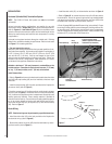
• Position the pressure switch (#3) on the fireplace cabinet bottom.
Refer to Figure 14 and Figure 18. Secure in position using Velcro strips
(#4) provided. Install vacuum hose to the pressure switch. Secure with
hose clamp (#8).
Figure 17
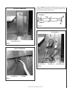
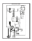
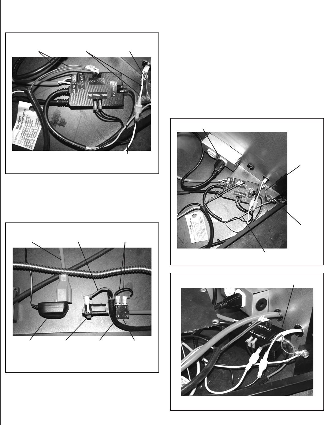
• Connect four-wire harness (#2) to the control module (#4) (Figure
17 ) at T-STAT (Red) and V-SWITCH (Black). Connect the other end
of the four-wire harness to the unit/wall On/Off switch and pressure
switch (#3) (Figure 18 ), black to the pressure switch, red to the
On/Off switch.
Figure 18
• Connect the transformer (3V) to the control module system power.
(Refer to Figure 18 ).
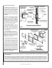
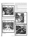
• Connect control module (#4) (To Power Vent) to the power wire
for the power vent termination. Remove the paint plug from the
fireplace corner post to expose the bare metal at the grounding point
and connect the PV (Romex ground wire) ground with the Control
Module ground wire to the grounding point with the screw provided.
See Figure 19.
• Connect the control module (#4) power plug to the power socket.
(See Figure 19 ).
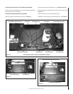
• Refer to Figure 14 and ensure all components are properly placed.
Ensure the ON/Off switch is secure and the pressure switch is in place.
Ensure the fireplace blower (if used) is installed and connected to
the power socket.
• Place the control module (#4) into position. Secure in position us-
ing Velcro strips provided. See Figure 20 and refer to Figure 14.
Figure 20
Figure 19
Control Module Ground
Two Brown Wires
From On/Off Switch
Wires To DV
Termnation
Termination
Ground
Two 3/16” Wires
(Black)
Two 1/4” Wires
(Red)
Control Module (4)
System Power Cord
Power Supply
Transformer
On/Off Switch
(Wall)
Four-Wire
Harness (2)
Pressure
Switch (3)
Control Module (4)
Power Vent
Ground
Control Module Power Plug
Control Module Ground
Ground
Point


