


9
NOTE: DIAGRAMS & ILLUSTRATIONS ARE NOT TO SCALE
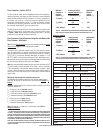
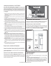
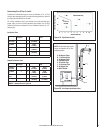
Figure 10 - Damper Adjustment, Free-Standing Models
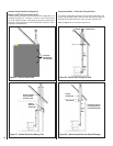
Installing Surround Assembly - Profi le
®
30 INS-2
(to be done after venting system is installed) This fi replace insert
requires surround panels (a set of metal panels that enclose the fi replace
opening when fi tted together). There is also a trim assembly that frames
the surround assembly to give it an attractive fi nished appearance. Put
the surround assembly together according to the following instructions
(ref. Page 41).
1. Remove panels and trim brackets from package. Be careful not to
discard the “L” shaped trim brackets which are attached to the sur-
round wrapping.
2. Open the hopper lid of the insert so it is out of the way for when panels
are installed.
3. Install the control board onto the right side panel (with door) using
the TEK screw (#8 x 1/2”) provided.
4. Position the power cord so that it will be behind either the right or left
side surround panel when they are installed.
5. Install right side surround panel onto right side of the insert body by
sliding the 2 fl anges on side of panel into corresponding slots on the
insert.
6. Connect the wiring harness from the insert into corresponding con-
nector on control board.
7. Locate damper rod on left side of the insert. Rotate angled arm of rod
so it is pointing down. Remove damper knob and set aside.
8. Install the left-hand panel onto the left side of the insert body by
sliding the 2 fl anges on side of panel into corresponding slots on the
insert.
9. Reach behind left surround panel and rotate damper arm so that end
is inserted into the upper right hand slot of left surround panel (see
Figure 11).
10. Reinstall damper knob by threading it onto end of damper rod.
11. Set the top surround panel in place over the two side panels. Posi-
tion the 2 tabs on bottom of top surround panel so they slide into
corresponding clips on the insert. Connect the top surround panel to
the side panels by pressing pins from side panels into corresponding
holes on top panel.
12. Remove the surround trim from its packaging. Assemble it together
using the corner keys (“L” shaped brackets) provided. Slide assembled
trim over the top surround panel and slide it down over the side
panels.
13. Push the Profi le 30 INS-2 back into place so the surround assembly
is fl ush with the face of the hearth.
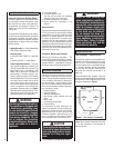
Damper Location, Installation And Adjustment
Damper Air Control Handle - Models: Profi le 20 FS-2 and Profi le 30 FS-2
(located on right side panel on model Profi le 20 FS-2 and on the left side
panel on Profi le 30 FS-2)
Adjustment Procedure- Models: Profi le
20 FS-2 and Profi le 30 FS-2
Loosen setscrew on set collar (see Figure 10), then adjust in 1/4” incre-
ments until optimum combustion air fl ow is achieved. For less air push
in and for more air pull out. After adjustment, position set collar against
side panel and tighten setscrew.
Damper is factory set to a
gap as specifi ed below.
1-5/8”
-
Profi le 30 FS-2
2”
-
Profi le 20 FS-2
To adjust, use a 3/32” allen
wrench (provided with stove)
to loosen set collar.
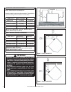
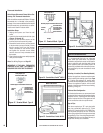
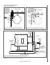
Damper Installation - Model: Profi le 30 INS-2
Install damper rod knob as illustrated (see Figure 11) and explained on
this page (see Installing Surround Assembly – Profi le 30 INS-2).
Adjustment Procedure - Model: Profi le 30 INS-2
The damper knob should be positioned in the center of the oblong slot
for the average installation (see Figure 11). If more or less air is needed,
then adjust in 1/4” increments until optimum combustion air fl ow is
achieved (see Damper Adjustment Guidelines on Page 21).
Left
Surround
Panel
For less air, slide
damper knob to the right
(or) for more air, slide
knob to the left.
Damper Knob
More Air
Less Air
Figure 11 - Damper Adjustment, Inserts
Profi le
30-2 INS
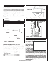
Hopper Cover Installation
Model: Profi le 30 INS-2
Install the hopper cover over the hopper using the 11 screws provided
as follows:
1) Align the 11 slots on the hopper cover with the corresponding 11
holes on the back and sides of the hopper.
2) Loosely install the 11 screws through the slots into the corresponding
holes in hopper (screws are provided in the accessory package).
3) Position the hopper cover to the highest position that will allow for
proper fi t into the fi replace opening, then tighten screws.