


10
NOTE: DIAGRAMS & ILLUSTRATIONS ARE NOT TO SCALE
Thermostat Installation:
Note: Always Disconnect Power Before Per-
forming The Thermostat Installation.
A 24 volt wall thermostat and 20 feet of 18-gage
thermostat wire is included in the accessory
package. It is recommended that the thermostat
and thermostat wire be installed by an autho-
rized Lennox Hearth Products dealer.
Installation Steps:
1. Unplug stove power cord from the wall
outlet.
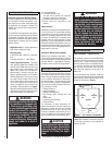
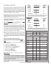
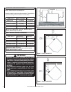
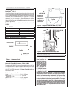
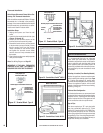
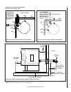
2. Locate the thermostat terminal block (see
Figures 12 through 16).
3. Loosen the two terminal screws on the
terminal block and remove the jumper.
4. Connect the two wires from your thermostat
to the terminals (one per terminal). Ensure
that the purple wires from the harness
remain connected to the terminal block
and tighten the terminal screws. Make
sure the wires are fi rmly connected to the
thermostat.
5. Plug in the stove and you are ready to operate
with your thermostat!
Note: See Wiring Diagram on Page 32.
IMPORTANT: IF THE WALL THERMOSTAT
PROVIDED IS NOT USED, THE JUMPER IS
REQUIRED FOR THE STOVE TO OPERATE.
Jumper
Leave jumper on, if
thermostat is NOT used
Remove jumper if Thermostat IS to be used
Terminal
Block
Thermostat wires
and purple wires
from wire harness
will connect to
these 2 terminals
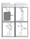
Jumper
Leave jumper on, if
thermostat is NOT used
Jumper
Remove jumper if Thermostat IS to be used
Thermostat wires
and purple wires
from wire harness
will connect to
these 2 terminals
Terminal
Block
Jumper
Model: Profi le 30 FS-2
Figure 12 - Terminal Block - Type A
Figure 13 - Terminal Block - Type B
Figure 14 - Terminal Block, Profi le
®
20FS-2
It is recommended that only an authorized
dealer install your pellet stove. The specifi ed
installation requirements must be followed to
ensure conformity with both the safety listing
of the appliance and local building codes. All
clearances, installation instructions and precau-
tions specifi ed by the vent manufacturer must
be followed.
Selecting a Location (Free-Standing Models)
Review the appliance clearance requirements
before installing the venting system (see Page
6). Position the appliance far enough away
from walls to allow adequate room for servicing.
Choose the appliance location with the least
amount of interference with the house framing,
plumbing, wiring, etc.
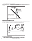
Preferred Vent Confi guration
For the best performance, we recommend a vent
run design which runs vertically and terminates
above the roof line. This design will allow natural
draft to improve the fl ow of fl ue gases and will
aid in combustion and stove performance.
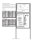
Type of Pipe
This stove requires type “PL” vent pipe (pellet
vent pipe, sometimes referred to as “L-Vent
pellet vent”), listed to UL 641 or ULC S609. Con-
nect the pellet vent pipe or the “tee” to the fl ue
collar using a minimum of three screws and seal
as specifi ed in “Pipe / Liner Joint Requirements”
on Page 11. Do not use class B gas chimney or
single wall chimney as a substitute.
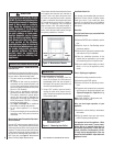
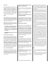
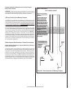
Terminal Block
Terminal Block
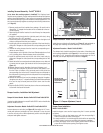
Terminal Block
VENTING REQUIREMENTS
Figure 15 - Terminal Block, Profi le 30 FS-2
Figure 16 - Terminal Block, Profi le 30 INS-2