6
CFI230J
23
CFI230J
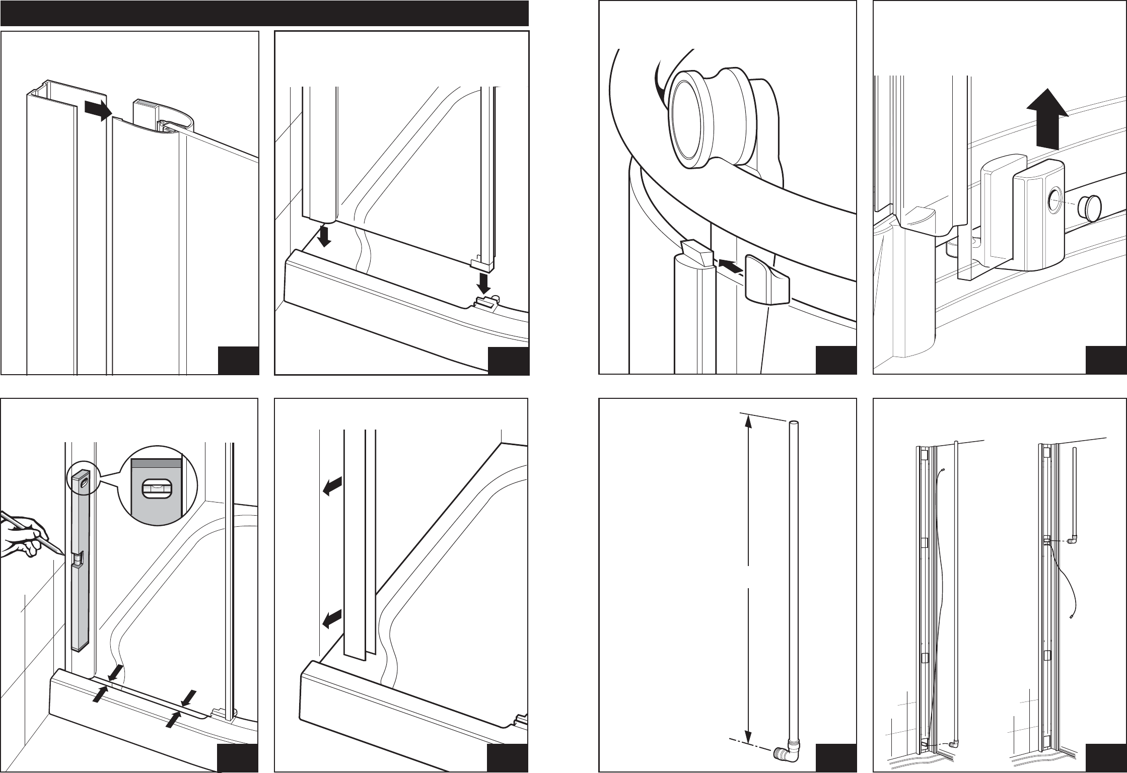
Remove wall channel from jamb and place
against mark on wall
Adjust wall jamb until glass is parallel to the
edge of the tray ‘A’. When jamb is vertical mark
edge of wall channel on the wall ‘B’.
STEP
1
ENCLOSURE INSTALLATION
Non Water Delivery Side only
Loosely fit wall channel into glass panel jamb
STEP
2
STEP
4
STEP
3
Carefully lift the assembly onto the tray. The end
of the glass panel fits into slot ‘A’ on the tray.
The wall channel end sits on the flat section of
the tray ‘B’
Fit roller securing caps to both top roller brackets.
Caps will ‘click’ and lock in place
STEP
35
STEP
37
STEP
36
Lift bottom roller up and tighten the fixing
screw with a 3mm allen key.
Fit the cap to cover the screw
A
Cut the 2 metre pipe
to size. Measure from
the centre line of the
connector.
Bottom Entry
‘A’ = 1750mm
Top Entry
‘A’ = 320mm
STEP
34
Bottom Entry Top Entry
Connect pipework
A
B
A
B
B
±0mm


