


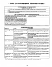
- HOW YOUR REVERSE OSMOSIS SYSTEM WORKS -
PREFILTER
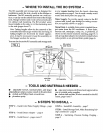
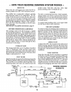
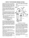
Water from the cold supply pipe enters the RO as-
sembly prefilter first (FIG. 8 and schematic below).
The prefilter has a replaceable sediment cartridge
with activated carbon in its composition. The car-
tridge (10 micron) removes sand, silt, dirt, other sedi-
ments, and up to the ppm of chlorine shown in the
specifications from the feed water. Chlorine will de-
stroy the RO membrane. Filtered, clean, chlorine-
free water flows from the prefilter, to the RO mem-
brane cartridge.
IMPORTANT... See pref!lter maintenance, page 11.
REVERSE OSMOSIS (RO) CARTRIDGE
The cartridge inside of the RO housing is a tightly
wound special membrane. The membrane removes
the dissolved solids and organic matter when water
is forced through the cartridge. High quality product
water (about I ounce per minute) exits the RO hous-
ing and goes to the storage tank or to the postfilter
and RO faucet. Reject water, with the dissolved sol-
ids and organic matter, is routed through the flow
control and to the drain.
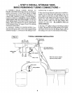
STORAGE TANK
The storage tank holds up to 2.3 gallons of product
water. A diaphragm inside the tank keeps water
pressurized to about 30 psi, when the tank is full, to
provide fast flow from the RO faucet. The tank when
empty, is pressurized to 5 - 7 psi.
POST FILTER
After leaving the storage tank but before going to the
RO faucet, product water goes through the post filter.
The post filter is an activated carbon type filter. Any
remaining tastes and odors are removed from the
product water. Taste-free, odor-free, clean, high
quality drinking water is available for use.
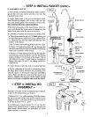
FAUCET
The sink or countertop faucet has a hand operated,
spring-loaded closed lever to prevent the waste of
drinking water. You can also keep the faucet open by
pushing upward on the lever and locking it against
the faucet spout.
To comply with plumbing codes, an air- gap is built
into the faucet drain water connection.
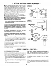
SHUTOFF ASSEMBLY
To conserve water, the drinking water system has an
automatic shutoff system. When the storage tank has
filled to capacity, and the drinking water faucet is
closed, pressure closes the shutoff to stop flow into
the RO. Pressure in the storage tank is about half of
the water supply pressure. After drinking water is
used, and pressure in the system drops, the shutoff
opens to allow water flow again.
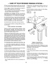
CHECK VALVE
A check valve (FIG. 10) is located in the outlet end of
the RO housing, opposite of the cap. The check valve
prevents a backward flow of product water from the
storage tank. A backward flow could rupture the RO
membrane.
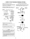
FLOW CONTROL
Water flow through the RO membrane is regulated
by the flow control. It maintains the desired flow rate
to obtain the highest quality drinking water. The
flow controlis located in the end of the 1/ 4" red drain
tubing, at the RO housing drain port. A small cone-
shaped screen fits over the end of the flow control to
help prevent plugging with drain water sediments.
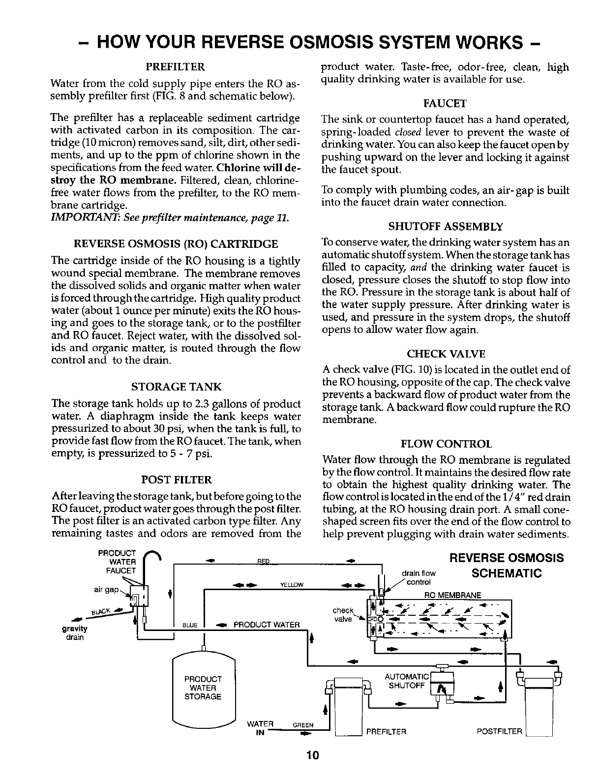
gravity
drain
PRODUCT
WATER
FAUCET
,,la=_l,,. YELLOW
'1
BLUE _ PRODUCT WATER
WATER GREEN
IN
1
. REVERSE OSMOSIS
II./1' d_a,_nt_oOlW SCHEMATIC
,,ele
rl]_ _'w RO MEMBRANE
[ l&l&t' '*,I _& .q.._ .,__. .__._
check I_I:___ " ;_ f f _ •
valve_._O _= - -- _.-- -- _t=-- -- --
l,_p AUTOMATIC [_ ,,,,e=
SHUTOFF [_
REFILT: I
10