


SERVICE TECH. INFORMATION
SECTION 5
22
5A. TROUBLESHOOTING
AUTOMATIC ELECTRONIC DIAGNOSTICS
The faceplate timer (PWA) computer has a self-diag-
nostic function for the electrical system, except for
input power and water meter.
The computer monitors the elec-
tronic components and circuits
for correct operation. If a mal-
function occurs, an error code
appears in the faceplate display.
The chart below shows the error codes that could
appear, and the possible defects for each code.
While an error code appears in the display, all face
plate buttons are inoperable except the SELECT
button. SELECT remains operational so the service
person can make the MANUAL INITIATED ELEC-
TRONIC DIAGNOSTICS (below) to further isolate
the defect, and check the water meter.
CODE
POSSIBLE DEFECT
MOST LIKELY LESS LIKELY
Err1, Err3,
E
r
r
4
wiring harness or connection to switch / position switch / motor inoperative / valve defect causing
h
i
g
h
t
o
r
q
u
e
E
r
r
1
,
E
r
r
3
,
Err4
w
i
r
i
n
g
h
a
r
n
e
s
s
o
r
c
o
n
n
e
c
t
i
o
n
t
o
s
w
i
t
c
h
/
p
o
s
i
t
i
o
n
s
w
i
t
c
h
/
m
o
t
o
r
i
n
o
p
e
r
a
t
i
v
e
/
v
a
l
v
e
d
e
f
e
c
t
c
a
u
s
i
n
g
high torque
E
r
r
4
h
i
g
h
t
o
r
q
u
e
See faceplate timer (PWA) replacement on page 23.
Err5 faceplate timer (PWA)
PROCEDURE FORREMOVING ERROR CODE FROM FACEPLATE: 1. Unplug transformer 2. Correct defect
3. Plug in transformer 4. Wait for 6 minutes. The error code will return if the defect was not corrected.
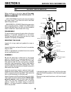
MANUAL INITIATED ELECTRONICS DIAG-
NOSTICS
1. To enter diagnostics¼
- -froma error codedisplay,press the#1 SELECT
button.
- -from a time display, press and hold the #1
SELECT button for 3 seconds.
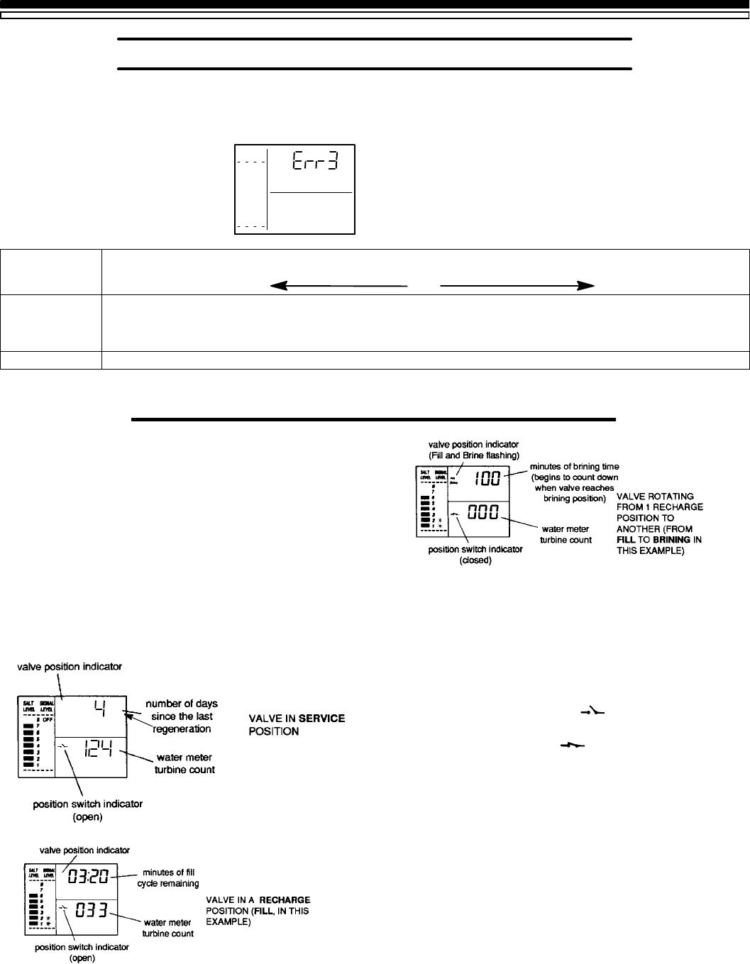
You will see 1 of the following displays. All of the
displays show what position the valve is in, if the
turbine is operating, and the position switch open or
closed status.
FLOW RATE
Serv
DAY
TIME REMAINING
FLOW RATE
Fill
TIME REMAINING
FLOW RATE
2. Press the ON/OFF-HOLD button to advance the
valve to the next position. To verify component
operation, or to possibly isolate a defect, observe
the following.
POSITION SWITCH STATUS: WIth the valve in
service, or any of the recharge cycles, the switch
indicator will show open . While the valve is
rotating from 1 position to another, the indicator will
show the switch closed . A defect is probable if
indications vary from this pattern.
WATER METER TURBINE: With soft water in use,
the turbine flow rate display continually repeats a
000 to 140 count for each gallon of water passing
through the turbine. The display will remain a
steady¼000 if soft water is not in use (open a nearby
soft water faucet to check).
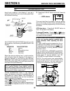
If you don’t get a reading in the display, with faucet
open, pull the sensor from the valve outlet port.Pass
a small magnet back and forth in front of the sensor.
You
8
7
6
5
4
3
2
1
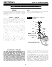
SALT
LEVEL
SIGNAL
LEVEL