


SECTION 6 REPAIRPARTS
I I
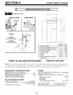
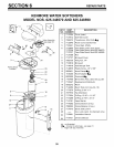
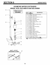
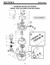
KENMORE WATER SOFTENERS
MODEL NOS. 625.348570 AND 625.348590
PARTS LIST
KEY PART
NO. NUMBER
50 7131755
51 7133008
52 0900857
53 7117808
54 0503288
55 7113927
56 7142942
57 0501228
58 7170327
59 7024160
60 0900431
61 7116713
62 0507369
63 0507615
64 7170335
42-3441
65 2207800
66 7170288
67 7134224
68 7170204
69 7092642
70 7129889
71 7081764
72 7082053
73 7170319
74 7081201
75 7081104
76 1202600
77 7095030
78 1148800
[]
[]
DESCRIPTION
Screw, #6-20 x 7/8 (2 req.)
Motor (Includes 2 ea. of Key No. 50)
Screw, #6-20 x 3/8 (2 req.)
Motor Plate
Bearing
Cam and Gear
Clip (Drain)
Flow Plug
O-Ring, 5/8 x 13/16
Drain Hose Adaptor
Hose Clamp OA
Clip (2 req.) OA
Installation Nut (2 req.) • []
Installation Tube (2 req.) • []
Washer (2 req.) • []
Install. Kit (JncLKey Nos. 62, 63 & 64) []
Installation Adaptor (2 req.) O[]
O-Ring, 15/16 x 1-3/16 (2 req.) O[]
Rotor Seal
O-Ring, 3/8 x 9/16
Plug (Drain Seal)
Spring
Seal (Nozzle & Venturi)
Valve Body
O-Ring, 1/4 x 3/8 (2 req.)
Retainer (Nozzle & Venturi)
Nozzle & Venturi Housing
Nut- Ferrule
Cone Screen
Flow Plug, .3 gpm
Parts included with Model No. 625.348590 only.
Parts included with Model No. 625.348570 only.
KEY PART
NO. NUMBER
79 7113032
80 7146043
81 7167659
82 7170262
83 7081188
84 7084607
85 7170246
86 7103964
87 7082087
88 7170212
89 7170238
90 7085263
91 7074123
92 7077472
93 7030713
94 7117816
95 7070412
96 7173707
97 2204101
98 7117858
99 9000803
7137507
7147112
7144821
7129716
42-3433
DESCRIPTION
Nozzle and Venturi -- Gasket Kit
Screen
Screen Support
O-Ring, 1-1/8 x 1-3/8
Cap
Flow Plug, .15 gpm
O-Ring, 3-3/8 x 3-5/8
Rotor & Disc
Wave Washer
O-Ring, 3/4 x 15/16
O-Ring, 7/16 x 5/8
Valve Cover
Screw, #10-14 x 2 (5 req.)
Expansion Pin
Switch
Spacer
Screw, #4-24 x 1-1/8 (flat head)
Sensor Housing
Turbine Support and Shaft
Turbine
O-Ring
Nozzle & Venturi Assy. (Includes
Key Nos. 75, and 77 through 84)
Parts Bag, Model No. 625.348570
(Includes parts marked with a O,
pages 28, 29 & 31) --order manu-
als separately, if needed.
Parts Bag, Model No. 625.348590
(incl. parts marked with a A, pages
28, 29 & 31) --order manuals sepa-
rately, if needed.
Seal Kit (Includes Key Nos. 67, 68,
71, 85, 88 and 89).
Drain Hose, 3/8" I.D. x 20' A[]
_I, not illustrated
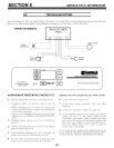
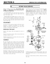
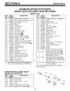
BYPASS INSTALLATION VALVE
MODEL NO. 625.34372
KEY PART
NO. NUMBER
100 0502206
101 7129863
102 7105013
103 7130911
104 7170288
42-3437
DESCRIPTION
Retainer Ring
Bypass Body
O-Ring, 13/16 x 1 (4 req.)
Stem
O-Ring, 15/16 x 1-3/16 (2 req.)
Bypass Valve (Complete) •[]
103
//
104
102
101
100
#
31