


SECTION 5 SERVICE TECH INFORMATION
I I
5A. TROU BLES HOOTI NG
AUTOMATIC ELECTRONIC DIAGNOSTICS
The face plate computer has a self-diagnostic
function for the electrical system (except input
power and water meter). The computer monitors the
electronic components and cir-
cuits for correct operation. If a _l-I- I
malfunction occurs, an error
code appears in the face plate
display.
The chart below shows the error codes that couM
appear, and the possible defects for each code.
While an error code appears in the display, all face
plate buttons are inoperable except the SELECT
button. SELECT remains operational so the service
person can make the MANUAL INITIATED ELEC-
TRONIC DIAGNOSTICS (below) to further isolate
the defect, and check the water meter.
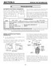
CODE
Err1
Err2
Err3
Err4
Err5
POSSIBLE DEFECT
MOST LIKELY _.., _ LESS LIKELY
motor inoperative / wiring harness or connection to switch / position switch / face plate
face plate
motor / face plate See face plate replacement on
face plate / position switch page 22.
face plate
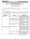
PROCEDURE FOR REMOVING ERROR CODE FROM FACE PLATE: 1. Unplug transformer 2. Correct defect
3. Plug in transformer 4. Wait for 6 minutes. The error code will return if the defect was not corrected.
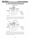
MANUAL INITIATED ELECTRONICS
DIAGNOSTICS
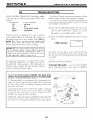
1. To enter diagnostics, press the SELECT button
and HoM for 3 seconds.
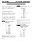
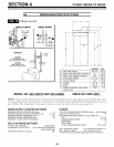
You will see the following display, showing valve
cycle position, position switch status ((7)pen or
closed), and turbine operation.
valve position indicator
........., I-I I-IN
5
4
position switch
indicator (open)
turbine count (wa-
ter flowing) _,
turbine count (no
water flowing)
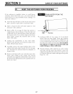
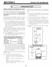
TURBINE OPERATION.. If no water is flowing through
the softener, the turbine indicator displays 3 zeros.
When water is flowing, the flow bar scrolls across the
display, and a 000 to 199 count repeats for each
gallon of water passing through the turbine. To
check for positive operation of the turbine if zeros
are shown, open a nearby soft water faucet and
observe the turbine count and flow bar.
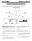
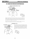
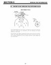
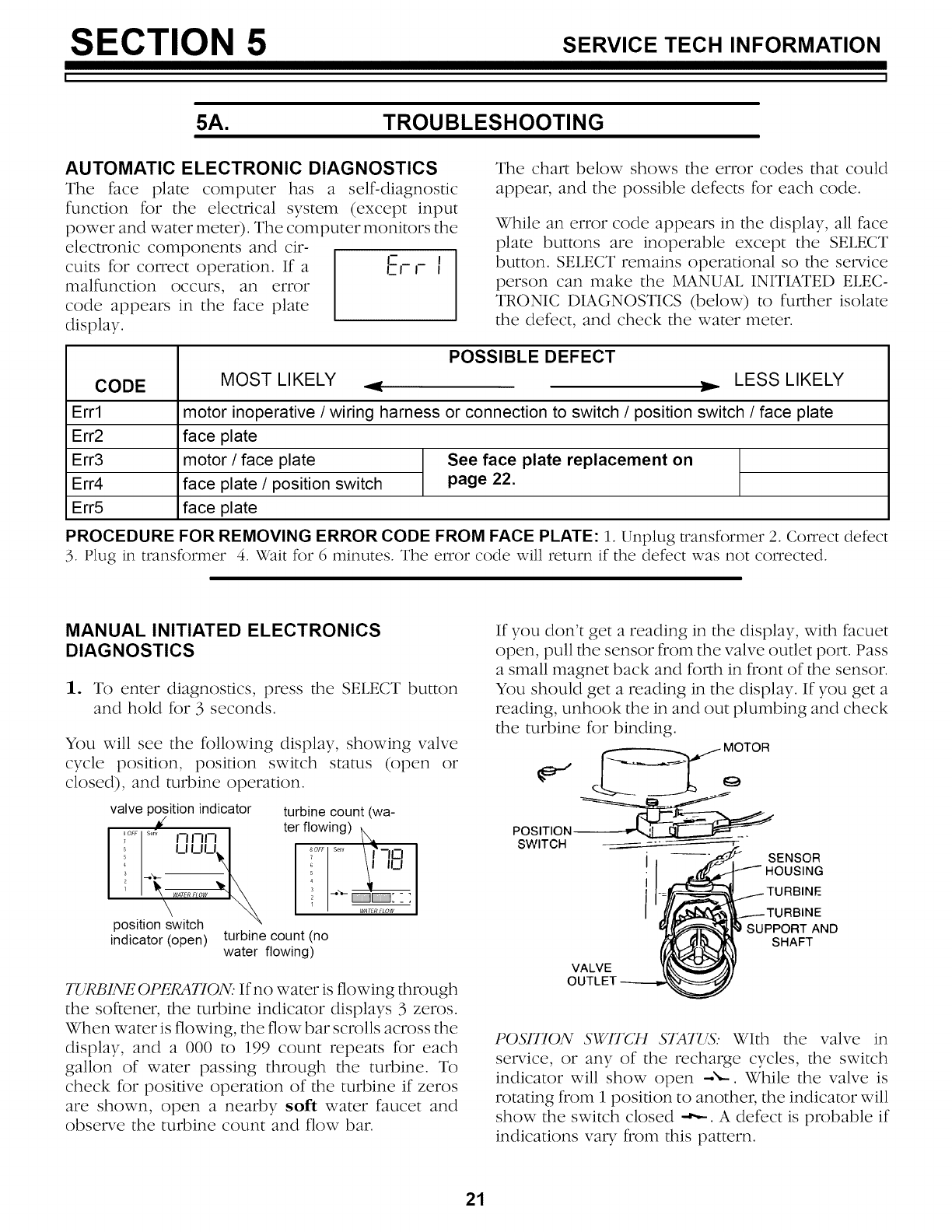
If you don't get a reading in the display, with facuet
open, pull the sensor from the valve outlet port. Pass
a small magnet back and forth in front of the sensor.
You should get a reading in the display. If you get a
reading, unhook the in and out plumbing and check
the turbine for binding.
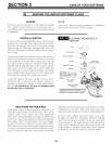
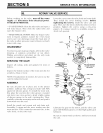
_ MOTOR
POSITION
SWITCH
VALVE
OL
SENSOR
HOUSING
IRBINE
lINE
_RT AND
SHAFT
POSITION SWITCH STAT{Z_: With the valve in
service, or any of the recharge cycles, the switch
indicator will show open --.",--. While the valve is
rotating from I position to another, the indicator will
show the switch closed -,',,-. A defect is probable if
indications yaw from this pattern.
21