


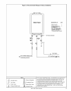
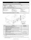

Location
Indoor models have their controller built into the front
panel. Additional controllers can also be installed.
• The controller should be out of reach of small
children.
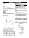
• Avoid locations where the controller may become hot
(near the oven or radiant heater).
• Avoid locations in direct sunlight. The digital display may
be difficult to read in direct sunlight.
• Avoid locations where the temperature controller could
be splashed with liquids.
• Do not install in locations where it can be adjusted by
the public.
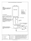
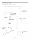
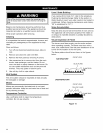
Configurations
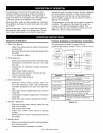
A maximum of 4 temperature controllers can be installed
for a water heater or bank of water heaters.
Controllers can only be wired in parallel. Controllers
cannot be wired in series.
If 4 temperature controllers are installed, simultaneously
press the Priority and On/Off buttons on the fourth
controller until a beep sounds.
Water
Heater
Controllers
Wire controllers in parallel
Figure 11
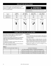
Cable Length and Size
The cable for the temperature controller should be a
non-polarized two-core cable with a minimum gauge
of 22 AWG. The maximum cable length from each
controller to the water heater depends on the total
number of wired controllers connected to the water
heater.
Table 9:
Number of Wired Maximum Cable Length for each
Controllers Controller to Water Heater
1 328 ft (100 m)
2 164 ft (50 m)
3 or 4 65 ft (20 m)
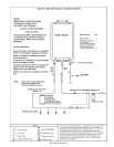
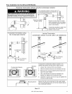
Mounting the Controller
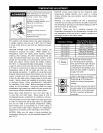
Do not attempt to connect the temperature controllers with
the power on. There is 120 volt potential, next to the
temperature controller connections inside the unit.
Do not connect the temperature controller to the 120VAC
terminals provided for the optional solenoid drain valves.
All service and wiring should be performed by a registered
installer.
Follow the procedure below to install additional
controllers.
1. Determine a suitable location for the controller.
2. Make three holes in the wall as shown.
3. Run the cable between the controller and the water
heater or the controller and the other controller.
4. Remove the face plate from the temperature controller
using a screwdriver.
5. Connect the cable to the temperature controller.
6. Mount the controller to the wall using the holes drilled
in step 2.
7. Disconnect the power from the water heater.
8. Remove the cover of the water heater.
9. Remove the plastic cover from the PCB and electrical
connections.
10. Thread the cable through the access hole at the base
of the unit and connect the wires to the controller
terminals on the right hand side bottom of the PCB.
11. Secure the controller cable using the clamp
provided.
12. Replace plastic cover over PCB and then replace the
cover of the water heater.
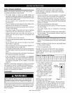
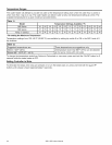
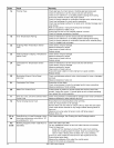
Outline of Controller
.......................................[
securing screw _),
"-- f
i 1-21/3z'i
wiring hole i-..... c_ j! _ _ _,._
i ..... ii 5-bl'le
securing .............C) i .............................................................{.......
CONNECTION TERMINALS
Figure 12
305 & 505 Indoor Manual 23