


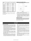
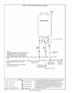
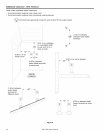

Figure 3: Freeze Protection Piping - Drawing
o o
Vacuum
Breaker
Water Heater
NOTE:
Heat trace (heat tape) ALL water pipe and fittings
located outside home (attic, crawl space) or
building structure. (ALL water pipe and fittings
shown above the dashed line in the drawing.)
NOTE:
ALL pipe and fittings shown below dashed line
should be located inside home or building
structure.
The vacuum breaker line should be located
inside the building structure.
J
0 0
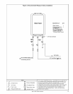
_] _--___ -- 3/4" Gas Connection
Minimum 3/4" Hot Water
Supply Line
1/2" Minimum
Normally Open
Solenoid Valve
D
3/4" Minimum Minimum 3/4"
Normally Closed Cold Water
Solenoid Valve Supply Line
Route to Floor Drain
i&
14
3/4" Ball Valve
3/4" Union
Check Valve
Pressure Relief Valve
KEY
_ Pressure Regulator
Circulating Pump
I-_ Boiler Drain Valve
[_ Solenoid Valve
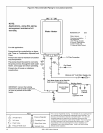
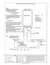
This is not an engineered drawing. It is intended only as a guide and not
as a replacement for professionally engineered project drawings. This
drawing is not intended to describe a complete system. It is up to the
contractor/engineer to determine the necessary components and
configuration of the particular system being installed. This drawing does
not imply compliance with local building code requirements. It is the
responsibility of the contractor/engineer to ensure installation is in
accordance with all local building codes. Confer with local building
officials before installation.
305 & 505 Indoor Manual