


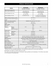
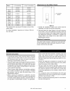

Table 1: to Combustibles to Non-Combustibles
305/505 305/505
Top of 6 inches 2 inches
Heater (152 mm) (51 mm)
Back of
0 (zero) 0 (zero)
Heater
Front of 6 inches 6 inches
Heater (152 mm) (152 mm)
Sides of 2 inches 1/2 inches
Heater (51 mm) (13 mm)
Floor/ 12 inches 12 inches
Ground (305 mm) (305 mm)
Vent 0 (zero) 0 (zero)
The clearance for servicing is 24 inches in front of the
water heater.
For closet installation: clearance is 6 inches (152 mm)
from the front.
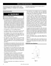
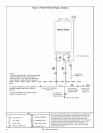
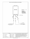
Attachment of the Water Heater
i+,o 0 o,_d
wall installation
brackets
,
,
Figure 2
Identify the installation location and confirm that the
installation will meet all required clearances.
Securely attach the water heater to the wall using any
of the holes in the wall installation brackets which are
at the top and bottom of the water heater. Ensure that
the attachment strength is sufficient to support the
weight. Refer to the weight of the water heater in the
Specifications section.
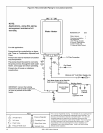
Electrical Connection
The water heater requires a standard 3 prong 120 VAC,
60 Hz properly grounded wall outlet. Plug the 6 ft long
power cord into the wall outlet.
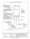
General Instructions
• A manual gas control valve must be placed in the gas
supply line to the water heater. A union can be used on
the connection above the shut off valve for the future
servicing or disconnection of the unit.
• Check the type of gas and the gas inlet pressure before
connecting the water heater. If the water heater is not of
the gas type that the building is supplied with, DO NOT
connect the water heater. Contact Sears for the proper
unit to match the gas type.
• Check the gas supply pressure immediately upstream
at a location provided by the gas company. Supplied
gas pressure must be within the limits shown in the
Specifications section.
• Before placing the appliance in operation all joints
including the heater must be checked for gas tightness
by means of leak detector solution, soap and water, or
an equivalent nonflammable solution, as applicable.
(Since some leak test solutions, including soap and
water, may cause corrosion or stress cracking, the
piping shall be rinsed with water after testing, unless it
has been determined that the leak test solution is non-
corrosive.)
• Always use approved connectors to connect the unit
to the gas line. Always purge the gas line of any debris
before connection to the water heater.
• The gas supply line shall be gas tight, sized, and so
installed as to provide a supply of gas sufficient to meet
the maximum demand of the heater and all other gas
consuming appliances at the location without loss of
pressure.
• Any compound used on the threaded joint of the gas
piping shall be a type which resists the action of liquefied
petroleum gas (propane / LPG).
• Refer to an approved pipe sizing chart if in doubt about
the size of the gas line.
305 & 505 Indoor Manual 11