


Installation Instructions (cont'd)
A WARNING
• The applianceanditsindividualshutoffvalvemustbe discon-
nectedfrom the gassupplypipingsystemduringanypressure
testingof the gassystem at test pressuresin excessof
poundpersquareinch(3.SkPa).
• The appliancemustbeisolatedfromthegassupplypipingsys-
tem by dosingitsindividualmanualshutoffvalveduringany
pressuretestingofthe gassupplypipingsystemat test pres-
suresequalor lessthan'/;poundper square inch(3.5k1_).
at WARNING [
Use pipe joint compound or teflon tape marked as being [
resistantto the actionof petroleum[Propene(I.R)] gase_ I
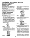
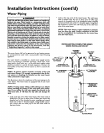
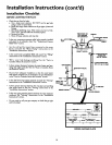
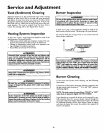
GAS PIPING WITH
FLEXIBLE CONNECTOR
GS,_JND IOINT
U NlON(Opti°n_l) _ CO_EO L
CAP
SEDIMENT TRAP
A sediment trap shall be installed as dose to the inlet of the
water heater as practical at the _me of water heater installation.
The sediment trap shall be either atee fitting with a capped nip-
ple in the bottom outlet or other device recognized as an effec-
tive sediment trap. If a tee fitting is used, it shall be installed in
conformance with one of the methods of installation shown
below.
Connecting the gas piping to the gas control valve of the water
heater can be accomplished by either of the two methods shown.
_,WARNING
Contaminantsin the gaslinesmaycauseimproperope_
of the gascomrol valvethat may resultin fire or explesion.
Beforeattachingthe gaslinebesurethat all gaspipeisclean
on the inside,To trap anydirt or foreignmaterial in the gas
supply line, a drip leg (sometimes called a sediment trap)
must be incorporated in the piping.The drip leg must be
readilyaccessible.Installin accordancewith the "Gas Piping"
section.Refer to the latest editionof the National FuelGas
JCode,ANSI Z223.1,alsoreferredto asNFPA 54.
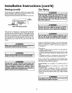
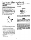
GAS PIPING WITH ALL BLACK IRON
PIPE TO GAS CONTROL
GROUND JOINT _ BLACK PIPE
UNlON(Opdonll) __ /
m_ GAS
CONTvALvEROL
3"
t,_ CAP
15