


Installation Instructions (cont'd)
,_ WARNING
•The applianceand itsindividualshutoffvalvemustbe discon-
nectedfrom the gassupplypipingsystemduringanypressure
testing of the gassystemat test pressuresin excessof ½
poundper squareinch(3.5kPa).
•The appliancemustbe isolatedfromthe gassupplypipingsys-
tem byclosingits individualmanualshutoffvalveduringany
pressuretestingof the gassupplypipingsystemat test pres-
suresequalor lessthan_ poundpersquareinch(3.5kPa).
_,WARNING I
Use pipe joint compound or teflon tape marked as being
resistant to the action of potro eum [Propane (LR)] gases.
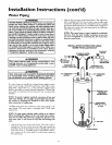
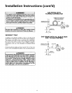
SEDIMENT TRAP
A sediment trap shall be installed as close to the inlet of the
water heater as practical at the time of water heater installation.
The sediment trap shall be either a tee fitting with a capped nip-
ple in the bottom outlet or other device recognized as an effec-
tive sediment trap. If a tee fitting is used, it shall be installed in
conformance with one of the methods of installation shown
below.
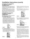
Connecting the gas piping to the gas control valve of the water
heater can be accomplished by either of the two methods shown.
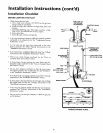
AWARNING
Contaminants in the gas lines may causeimproper operation
of the gas control valve that may result in fire or explosion.
Before attaching the gas line be sore that all gas pipe is clean
on the inside. To trap any dirt or foreign material in the gas
supply line, a drip leg (sometimes called a sediment trap)
must be incorporated in the piping. The drip leg must be
readily accessible. Install in accordance with the "Gas Piping"
section. Refer to the latest edition of the National Fuel Gas
Code, ANSI Z223.1, also referred to as NFPA 54.
GAS PIPING WITH
FLEXIBLE CONNECTOR
FLEXIBLEGAS CONNECTOR
GROUND IOINT_ _LOOP
,, __ CONTROLvALVE
3,,T..(sD, ='Po
GAS PIPING WITH ALL BLACK IRON
PIPE TO GAS CONTROL
GROUND JOINT BLACK PIPE
UNION(Optional)
3" m_in DRIP LEG
• (Sedimenttrap)
_1 CAP
GAS
CONTROL
VALVE
15