


Installation Instructions (cont'd)
_,WARNING
• The applianceand itsindividualshutoffvalvemustbe discon-
nectedfrom the gassupplypipingsystemduringanypressure
testingof the gas systemat test pressuresin excessof ½
poundpersquareinch(3.$1d_).
• The appliancemustbe isolatedfromthe gassupplypipingsys-
tern bydosingitsindividualmanualshutoff valveduringany
pressuretestingof the gassupplypipingsystemat test pres-
sur_ equalor lessthan _ poundper squareinch(3.SkPa).
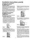
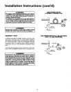
GAS PIPING WITH
FLEXIBLE CONNECTOR
LOOP
GAS
GROUNDJOIN] CONTROL
UNION(OpUonaI) VALVE
• _,WARNING
Use pipe ioint compound or teflon tape marked as being
resistantto theactionofpetro eum [Propane(LR)] gases.
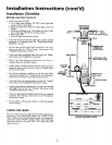
DRIP LEG
(Sediment trap)
CAP
SEDIMENT TRAP
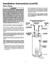
A sediment trap shall be installed as close to the inlet of the
water heater as practical at the time of water heater installation.
The sediment trap shall be either a tee fitting with acapped nip-
ple in the bottom outlet or other device recognized as an effec-
tive sediment trap. If a tee fitting is used, it shall be installed in
conformance with one of the methods of installation shown
below.
Connecting the gas piping to the gas control valve of the water
heater can be accomplished by either of the two methods shown.
AWARNING
Contaminantsin thegaslinesmaycauseimproper operation
of the gascoWa_lv':dvethat may resultin fire or expioslon.
Beforeattachingthe gaslinebe surethat allgaspipeisclean
on the inside.To trap anydirt or foreignmaterialin the gas
supplyline, a drip leg (sometimes calleda sedimenttrap)
must be incorporated in the piping•The drip leg must be
readilyaccessible.Installinaccordancewith the "Gas Piping"
section.Referto the latesteditionof the National Fuel Gas
Cede,ANSI Z223.1,alsoreferredto asNFPA54.
GAS PIPING WITH ALL BLACK IRON
PIPE TO GAS CONTROL
GROUND JOINT _ BLACK PIPE
UNION(Optional) __
GAS
CONTROL
VALVE
15