8. Connect the electrical supply to the water heater.
NOTE: Remove the standard 1/2 inch knock-out (opening)
in the junction box for conduit connections.
9. Connect ground wire to green ground wire in the electrical
junction box of the water heater.
10. Reinstall the junction box cover.
11. Reattach the left touvered access panel to the water
heater and secure it using the screws loosened earlier.
12. Turn on electrical power to the water heater.
13. Press the power button to turn the water heater on, then
press the Efficiency button to set the operating mode.
NOTE: The water heater wilt conduct a system diagnostic
(approximately 8 minutes) prior to operation.
14. Once the diagnostic sequence has finished, the
fan should turn on followed by the compressor.
NOTE: The heat pump's fan wilt not turn on if the incoming
water temperature is tess than 59 °F and/or the ambient
air temperature is above 109 °F or below 45 °F. Should the
internal diagnostics detect a problem with the heat pump,
an error message will be displayed.
15. Set the operational mode. For typical installation, the
Hybrid Mode offers the best combination of efficiency
and hot water delivery. For detailed descriptions of all
operational modes see "Adjusting the User Interface
Module/Operational Modes" section.
Green
Ground
Wire
Ground
Wire
Red Wire
Conduit
(Field Connection)
FIGURE 13.
Wiring Diagram
• Before removing any access
panels or servicing the water
heater, make sure the electrical
supply to the water heater is
turned "OFF".
• Failure to do this could result in
death, serious bodily injury, or
property damage.
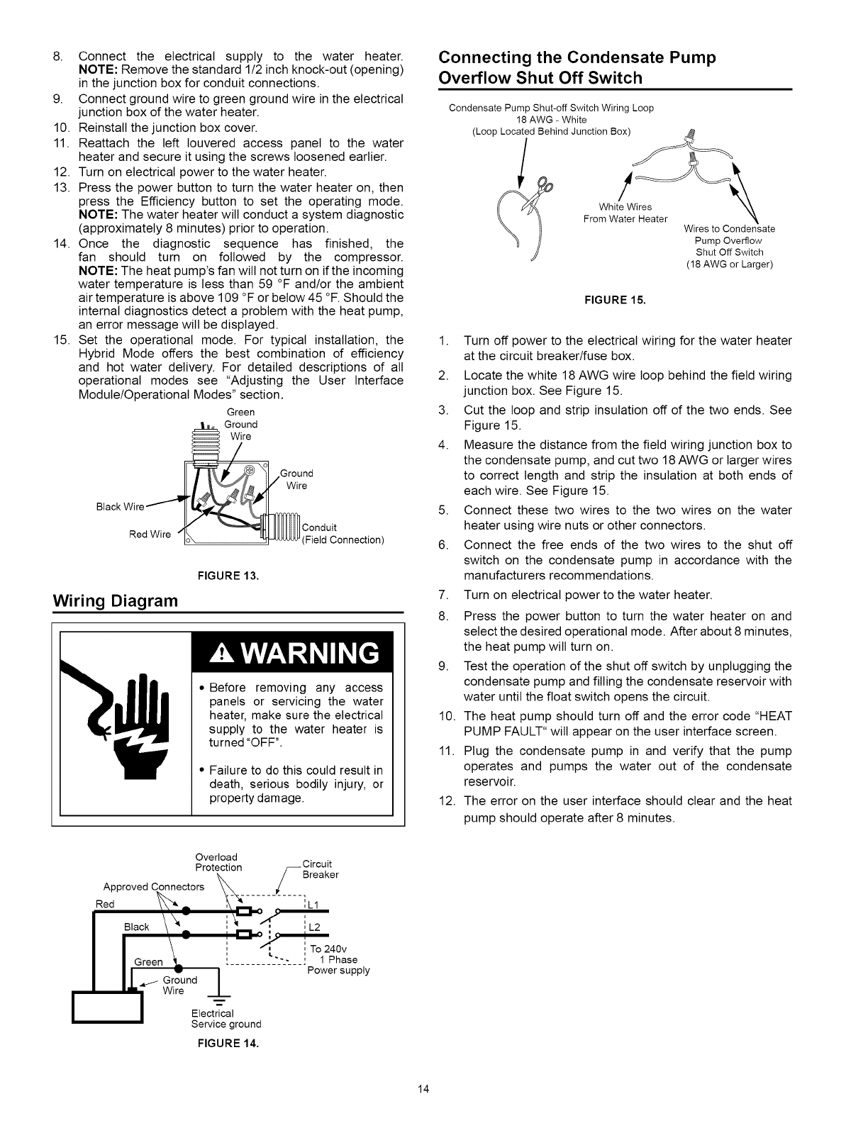
Connecting the Condensate Pump
Overflow Shut Off Switch
Condensate Pump Shut-off Switch Wiring Loop
18AWG - White
(Loop Located Behind Junction Box)
!
White Wires
From Water Heater
Wires to Condensate
Pump Overflow
Shut Off Switch
(18 AWG or Larger)
FIGURE 15.
1. Turn off power to the electrical wiring for the water heater
at the circuit breaker/fuse box.
2. Locate the white 18 AWG wire loop behind the field wiring
junction box. See Figure 15.
3. Cut the loop and strip insulation off of the two ends. See
Figure 15.
4. Measure the distance from the field wiring junction box to
the condensate pump, and cut two 18 AWG or larger wires
to correct length and strip the insulation at both ends of
each wire. See Figure 15.
5. Connect these two wires to the two wires on the water
heater using wire nuts or other connectors.
6. Connect the free ends of the two wires to the shut off
switch on the condensate pump in accordance with the
manufacturers recommendations.
7. Turn on electrical power to the water heater.
8. Press the power button to turn the water heater on and
select the desired operational mode. After about 8 minutes,
the heat pump will turn on.
9. Test the operation of the shut off switch by unplugging the
condensate pump and filling the condensate reservoir with
water until the float switch opens the circuit.
10. The heat pump should turn off and the error code "HEAT
PUMP FAULT" wilt appear on the user interface screen.
11. Plug the condensate pump in and verify that the pump
operates and pumps the water out of the condensate
reservoir.
12. The error on the user interface should clear and the heat
pump should operate after 8 minutes.
S CirreC_tr
ILl
iL2
_40v
s... 1 Phase
Power supply
Ground
Wire
1
Electrical
Service ground
FIGURE 14.
14


