


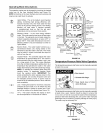

Temperature-Pressure Relief Valve
Explosion Hazard
Temperature-pressure relief valve
must comply with ANSI Z21.22
CSA 4.4 andASME code.
• Properly sized temperature-relief
valve must be installed in opening
provided.
• Can result in overheating and
excessive tank pressure.
• Can cause serious injury or death.
This heater is provided with a properly certified combination
temperature - pressure relief valve by the manufacturer.
The valve is certified by anationally recognized testing laboratory
that maintains periodic inspection of production of listed equipment
of materials as meeting the requirements for Relief Valves for Hot
Water Supply Systems, ANSI Z21.22 • CSA 4.4, and the code
requirements of ASME.
If replaced, the valve must meet the requirements of local codes,
but not less than a combination temperature and pressure relief
valve certified as indicated in the above paragraph.
The valve must be marked with a maximum set pressure not to
exceed the marked hydrostatic working pressure of the water
heater (150 psi = 1,035 kPa) and a discharge capacity not less
than the water heater input rate asshown on the model rating plate.
(For electric heaters, watts x 3.412 equals Btu/hr input rate)
For safe operation of the water heater, the relief valve must not be
removed from its designated opening nor plugged.
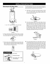
The temperature-pressure relief valve must be installed directly
into the fitting of the water heater designed for the relief valve.
Position the valve downward and provide tubing so that any
discharge will exit only within 6 inches (153 mm) above, or at any
distance below the structural floor. Be certain that no contact is
made with any live electrical part. The discharge opening must
not be blocked or reduced in size under any circumstances.
Excessive length, over 30 feet (9.14 m), or use of more than four
elbows can cause restriction and reduce the discharge capacity
of the valve.
Water Damage Hazard
• Temperature-pressure relief valve discharge
pipe must terminate at adequate drain.
No valve or other obstruction is to be placed between the relief
valve and the tank. Do not connect tubing directly to discharge
drain unless a 6 inch air gap is provided. To prevent bodily
injury, hazard to life, or property damage, the relief valve must
be allowed to discharge water inquantities should circumstances
demand. Ifthe discharge pipe is not connected to a drain or other
suitable means, the water flow may cause property damage.
The Discharge Pipe:
• Shall not be smaller in size than the outlet pipe size of the
valve, or have any reducing couplings or other restrictions.
• Shall not be plugged or blocked.
• Shall be of material listed for hot water distribution.
• Shall be installed so as to allow complete drainage of both the
temperature-pressure relief valve, and the discharge pipe.
• Shall terminate a maximum of six inches above afloor drain or
external to the building. In cold climates, it is recommended
that the discharge pipe be terminated at an adequate drain
inside the building.
Shall not have any valve between the relief valve and tank.
Water temperature over 125°F
(52°C) can cause severe burns
instantly resulting in severe injury
or death.
Children, the elderly, and the
physically or mentally disabled
are at highest riskfor scald injury.
Feel water before bathing or
showering.
Temperature limiting valves are
available.
Read instruction manual for safe
temperature setting
The temperatureipressure relief valve must be manually operated
at least once a year. Caution should be taken to ensure that
(1) no one is in front of or around the outlet of the temperature-
pressure relief valve discharge line, and (2) the water manually
discharged wilt not cause any bodily injury or property damage
because the water may be extremely hot.
If after manually operating the valve, it fails to completely reset
and continues to release water, immediately close the cold water
inlet to the water heater, follow the draining instructions, and
replace the temperature-pressure relief valve with a new one.
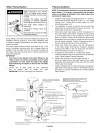
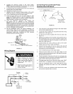
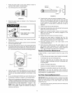
%errat re,,:Ta,ve
Discharge Pipe
(Do Not Ptug or Cap)
Drain Pan 2 1/2"
2DtP_t_ elVIsaXi_'_e_l_la_ d _
the water heater. _,,_ U_
Drain I_,ne_/_ _
ID Minimum
_'---_ 6_'Maximum
Drain
Air Gap
FIGURE 11.
12