


8. After piping has been properly connected to the water
heater, open the nearest hot water faucet. Then open the
cold water shut off valve and allow the tank to completely
fill with water. To purge the lines of any excess air and
sediment, keep the hot water faucet open for 3 minutes
after a constant flow of water is obtained. Close the faucet
and check all connections for leaks.
Please note the following:
• The system should be installed only with piping that is
suitable for potable (drinkable) water such as copper,
CPVC, or polybutylene. This water heater must not be
installed using iron piping or PVC water piping.
• Use only pumps, valves, or fittings that are compatible with
potable water.
• Use only full flow ball or gate valves. The use of valves
that may cause excessive restriction to water flow is not
recommended.
• Use only 95/5 tin-antimony or other equivalent solder. Any
lead based solder must not be used.
• Piping that has been treated with chromates, boiler seal, or
other chemicals must not be used.
• Chemicals that may contaminate the potable water supply
must not be added to the piping system.
Property Damage Hazard
• Avoid water heater damage.
• Install thermal expansion tank if necessary.
• Do not apply heat to cold water inlet.
• Contact qualified installer or service agency.
Condensate Drain Line Installation
Install two 1/2" PVC discharge lines from the condensate drains
(located on the right side near the back). The lines should
terminate a maximum of six inches above an adequate drain.
Do not discharge the condensate drain lines into the metal drain
pan. If no floor drain is available or the drain is above the level
of the condensate line, a condensate pump should be installed.
These pumps are available from local distributors.
When installing the drain line, note the following:
• Plastic pipe or tubing must be used to connect the
condensate drain to a suitable drain or condensate pump.
• Condensate drain lines should be installed in conditioned
areas only. Install approved insulation on the condensate
drain lines to prevent condensation from forming on the
outside of the drain lines. Condensation drain lines installed
in areas that are subject to freezing temperatures should
be wrapped with a nationally recognized/listed heat tape.
Install per manufacturer's instructions.
• Do not connect condensate drain lines with other drain or
discharge lines into a single (common) pipe or line. Each
line (condensate drain line, temperature and pressure relief
valve discharge pipe, etc) should be independently run to
an adequate drain.
• Slope the condensate drain lines toward the inside floor
drain or condensate pump.
• The condensate drain lines and connections to the drain
piping must comply with all local codes.
• Use appropriate primer and glue to cement the condensate
drain lines to the heat pump drain pan. NOTE: The heat
pump drain pan is ABS and the two condensate drain pipes
should be PVC.
• If a condensate pump is installed it should shut off the
heat pump in the event the condensate pump fails or the
float switch in the pump activates (See "Condensate Pump
Installation" section.)
T & P Valve and Pipe Insulation
NOTE: Your water heater is insulated to minimize heat
loss from the tank. Further reduction in heat loss can be
accomplished by insulating the hot water lines from the
water heater.
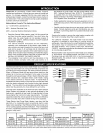
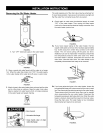
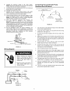
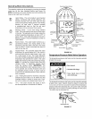
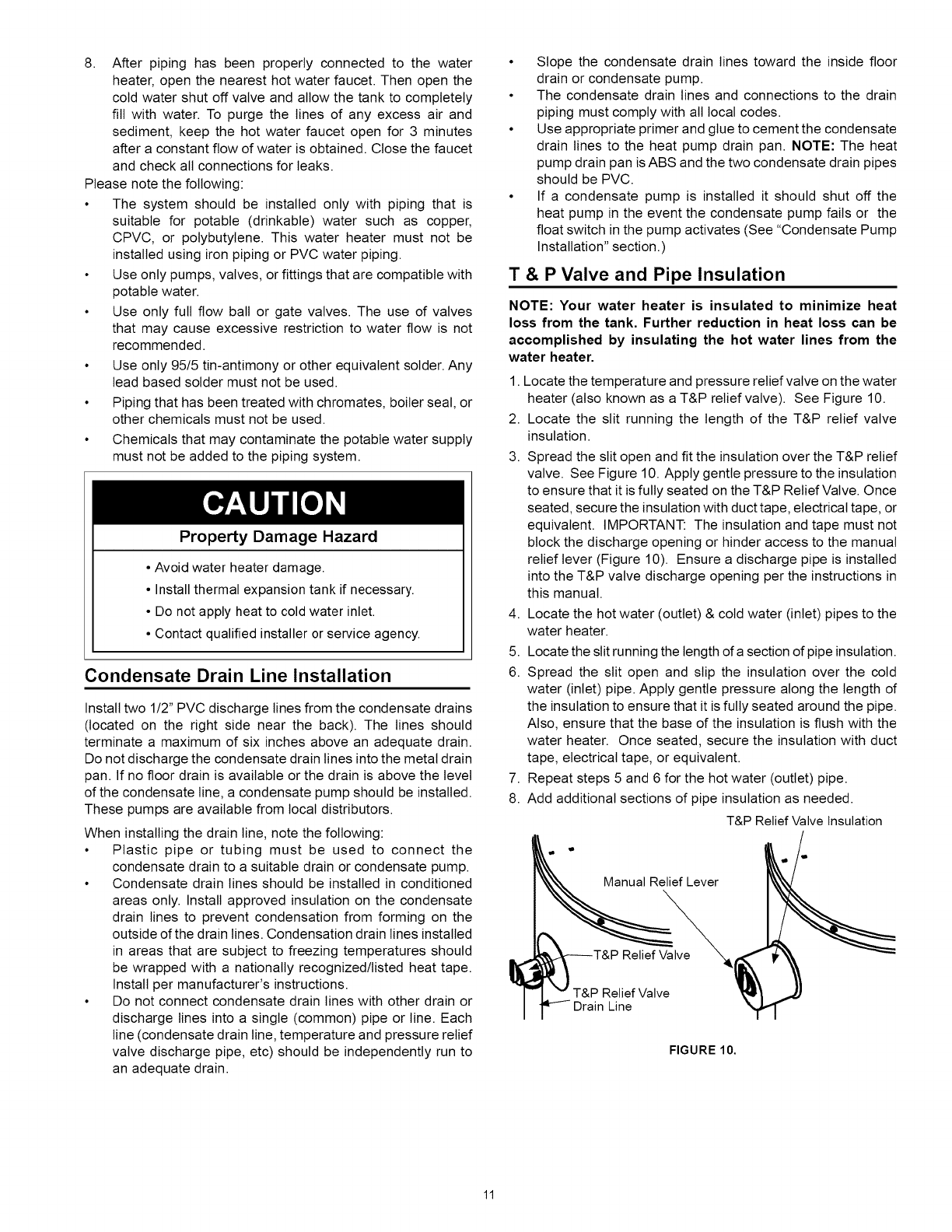
1. Locate the temperature and pressure relief valve on the water
heater (also known as a T&P relief valve). See Figure 10.
2. Locate the slit running the length of the T&P relief valve
insulation.
3. Spread the slit open and fit the insulation over the T&P relief
valve. See Figure 10. Apply gentle pressure to the insulation
to ensure that it isfully seated on the T&P Relief Valve. Once
seated, secure the insulation with duct tape, electrical tape, or
equivalent. IMPORTANT: The insulation and tape must not
block the discharge opening or hinder access to the manual
relief lever (Figure 10). Ensure a discharge pipe is installed
into the T&P valve discharge opening per the instructions in
this manual.
4. Locate the hot water (outlet) & cold water (inlet) pipes to the
water heater.
5. Locate the slit running the length of asection of pipe insulation.
6. Spread the slit open and slip the insulation over the cold
water (inlet) pipe. Apply gentle pressure along the length of
the insulation to ensure that it is fully seated around the pipe.
Also, ensure that the base of the insulation is flush with the
water heater. Once seated, secure the insulation with duct
tape, electrical tape, or equivalent.
7. Repeat steps 5 and 6 for the hot water (outlet) pipe.
8. Add additional sections of pipe insulation as needed.
T&P Relief Valve Insulation
ef Lever
veX
Relief Valve
Drain Line
FIGURE 10.
11