21
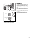
Blower Installation
1. Run the 10 ft. power cord out from the fireplace
to the nearest grounded power outlet.
2. With the Speed Control in either the HI or LOW
position, the fan will power on when the firebox
comes up to operating temperature. (approxi-
mately 10 -20 minutes). See the Operation section
for further details.
Blower Power Requirement
The blower must be electrically grounded in accor-
dance with local codes or, in the absence of local
codes, with the current NFPA 70- National Electrical
Code or CSA C22.1-Canadian Code.
A three-prong (grounding) power supply plug is
included for protection against shock hazard and
should be plugged directly into a properly grounded
three-prong receptacle. DO NOT CUT OR REMOVE
THE GROUNDING PRONG FROM THE PLUG.
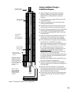
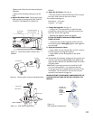
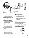
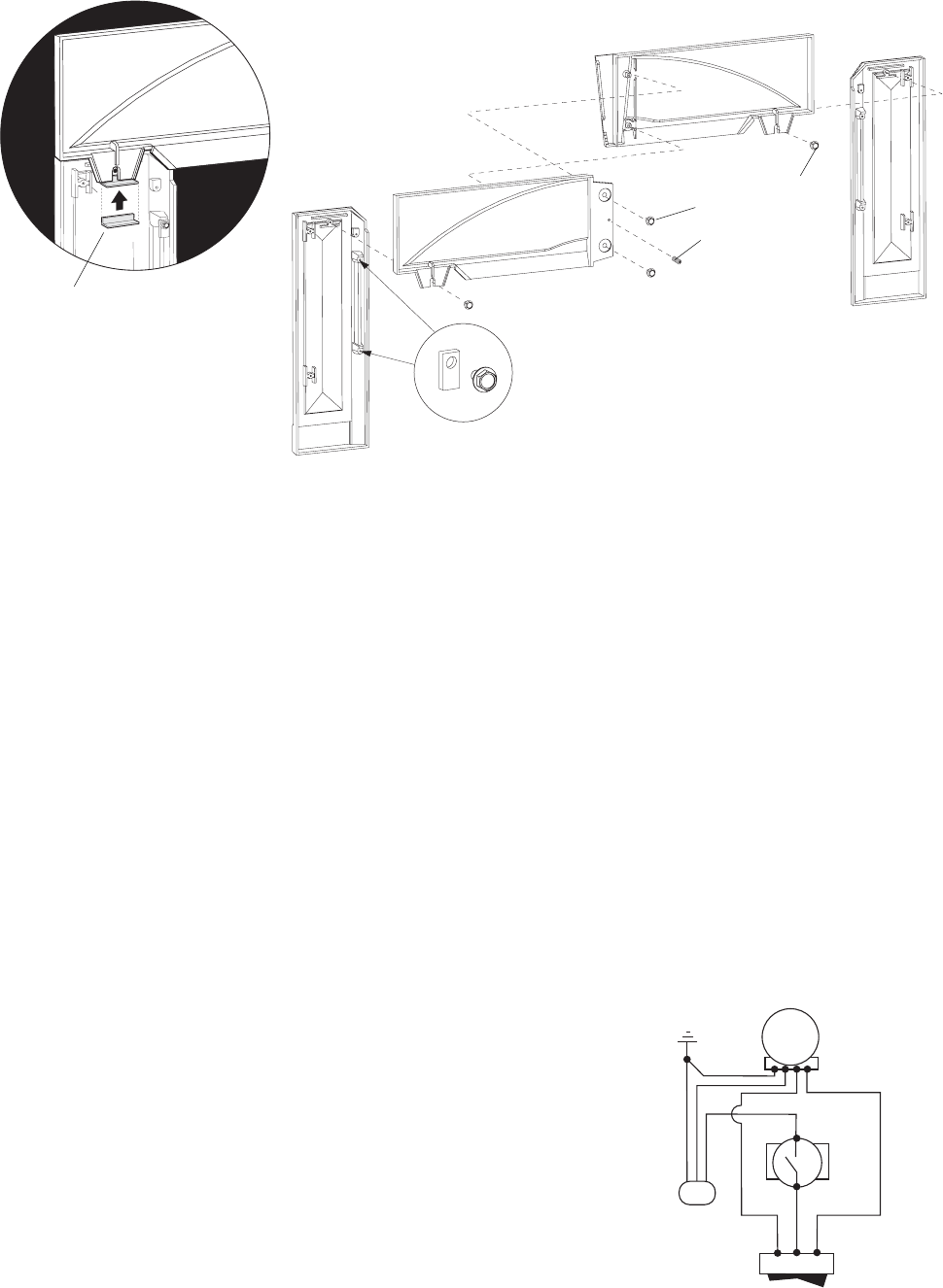
Right Breastplate
Left Breastplate
Left Leg
Right
Leg
Hanger Tabs, 4
(pre-installed)
Figure 24.
Assemble the
Surround Panels.
Surround Assembly
1. Layout the parts. Place the castings face down
on a protective surface such as carpeting,
blankets or a sheet of cardboard.
2. Attach the Breastplates together using two M6
x 10 hex head flange bolts. Do not tighten. Use
the hex key found in the Hardware Bag to adjust
the set screw until a flush fit is attained, then
tighten the bolts.
3. Attach the Leg panels to the Breastplates:
The Legs must be oriented with the Hanger Tabs
on the inside edges as in the drawing above. Use
two M6 x 12 hex head flange bolts to attach the
Legs to the Breastplate assembly.
4. Adjust plumb if necessary. Lift the surround
assembly upright and check the plumb of the
legs and breastplates. Look at the assembly
from the side; the breastplates and legs should
be aligned straight. If the assembly is bowed,
loosen the attachment bolt enough to insert a
shim as shown in the detail above, then re-
tighten.
5. If you will be installing the optional Wide
Surround Panels, use the instructions included
with that kit.
6. Attach the Assembly to the Firebox. Lift the
entire assembly upright and position it in front
of the insert firebox. The four hanger tabs on the
surround legs must engage with the adjacent
holes in the two brackets on either side of the
firebox opening. The surround will easily engage
with these brackets if the firebox is slightly
proud of the fireplace opening.
Hang the surround assembly on the firebox and
push the entire unit into position so that the
surround is flush against the fireplace face.
Plumb
Adjustment
Shim (2)
Set Screw
M6 x 12 Hex Bolt, (2)
M6 x 10 Hex Bolt, (2)
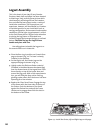
SWITCH
SNAPSTAT
WHITE
BLACK
RED
BLACK
BLACK
RED
WHITE
GREEN
BLOWER
POWER
SUPPLY
HI OFF LO
Figure 25.
Blower Wiring Diagram


